[ Summary | DETAILS | CONCLUSION | References ]
Summary
本研究の目的は、乗り物において死角領域を透視表示する視野外情報提示システムの構築である。ディスプレイ方式として再帰性反射材にプロジェクタで映像を投影する再帰性投影技術(RPT: Retro-reflective Projection Technology)を用いることで、乗り物の内壁部分に視野内情報と連続的に明るさや大きさなどの違和感なく視野外情報を提示できる。すなわち、乗り物の床、ドア、ピラーといった内壁部分に再帰性反射材を貼り、車外カメラで得た視野外情報を再帰性投影することで、内壁部分があたかも透明な窓であるかのような状況を実現できる。自動車はもとよりヘリコプターにこの機能を搭載すれば、床部分に提示された地面を見ながら安全に離着陸を行うことも可能となる。
DETAILS
Transparent Cockpit
The experience of driving a car would be quite different and attractive if the car was to be transparent, as if it was made of glass. In such a scenario, you would not only enjoy a 360° view around you through the windows but also a view through the body of the car that would give you the impression of flying a few feet above the road surface. Such a Transparent Cockpit would be far safer and far more enjoyable than the cockpit that is currently available in cars, which affords a fairly restricted view of what lies ahead and an even more restricted view of what lies behind.
For the purpose of safety and increased operability, it is important to obtain a wide field of view while driving a car. However, cars typically feature limited space for glass windows. In this light, the concept of a Transparent Cockpit, in which an image of an object that is currently located in a blind spot is displayed on the inner wall of the car as if it is transparent, is quite attractive. In this system, internal components of the car, such as the doors, backseats, and floor, are virtually transparent. This completely eliminates blind spots, and objects that would otherwise be occluded by structural elements are observed as if through a window.
A Transparent Cockpit can be used not only in passenger cars but also in other vehicles such as helicopters or airplanes, the floor of which if made virtually transparent can aid the pilot in landing more easily (Fig.1).
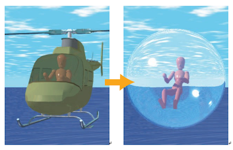
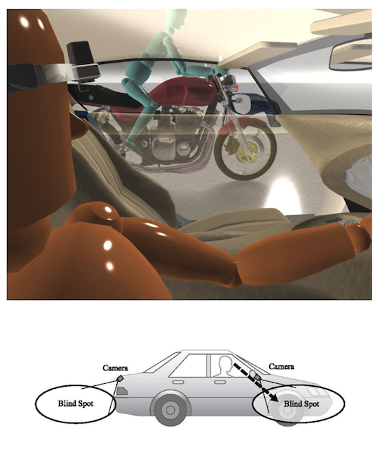
Fig.1 Conceptual Images of Transparent Cockpit: Ideal (above) and Near Future (below).
In a car with a Transparent Cockpit, all internal components such as doors and seats must be virtually transparent, i.e., the driver must be able to see the outside environment as if these components are not there at all. The scenery through the internal components must be seamlessly connected to that viewed through the windows of the car.
The Transparent Cockpit system consists of an external camera system and an internal display system. Cameras are placed all around the vehicle to capture images of the surroundings. These images are processed as if they are viewed from the driver’s viewpoint and displayed on the internal components of the car.
Two types of display systems can be considered. One is an autostereoscopic display made of LCDs, LEDs, or OLEDs that is installed on the internal components of the car. However, it is currently very difficult to fabricate such displays to fit the varied shapes of dashboards, window pillars, doors, floor, and seats. In particular, seats are usually made of fabrics and are therefore unsuitable for installing fixed-type visual displays. Thus, the use of autostereoscopic displays made of OLEDs, while quite promising, is currently infeasible.
The other is a system using projectors. In this case, the internal components need only serve as screens—either by having a screen placed on them or by being made of a material that can be used as a screen—which is much easier to implement. Therefore, the use of projection technology is currently not only promising but also much more feasible.
However, several problems need to be solved for projectors to be used for displaying the outside environment using conventional projection technology.
(1) Brightness of the projected image is not sufficiently high to match that of the scenery observed through windows, especially in the daytime.
(2) When an image is projected on a complex-shaped screen such as dashboards or seats, it will be distorted, thus necessitating distortion correction.
(3) Special eyewear such as shutter glasses is necessary to observe stereo 3D images, without which the outside scenery would be observed as if on a screen.
(4) Projection of multiple images on the same screen is not possible, thus preventing multiple users from seeing their own scenery according to their viewpoint.
These problems of conventional projection technology can be solved by using Retroreflective Projection Technology (RPT). RPT makes it possible to transform any physical object into a virtual object simply by covering its surface with a retroreflective material.
In an RPT configuration, a projector is placed at the axial symmetric position of the user’s eyes, with a half-mirror used as a reference, and a pinhole is placed in front of the projector to ensure adequate depth of field, as shown in Figure 2. This condition is referred to as the “conjugate optical condition,” which is the principle of RPT. Images are projected onto a screen that is constructed, painted, or covered with a retroreflective material.
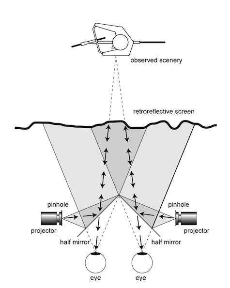
Fig. 2 Principle of RPT system.
Conventional screens scatter projected light equally in all directions, as in the case of a Lambertian surface. In contrast, retroreflective surfaces reflect projected light only in the direction of projection (Fig. 3).
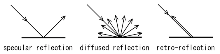
Fig. 3 Three typical reflection patterns.
Figure 4 shows how a retroreflective surface behaves. The retroreflective surface is covered with microscopic beads of 50-µm diameter that reflect incident light back along the direction of incidence. This effect can also be achieved by using the microstructure of prism-shaped retroreflectors that are densely distributed on the surface.
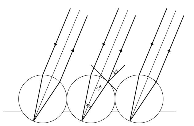
Fig. 4 Retroreflective surface densely covered with microscopic beads of 50-µm diameter. Ideally, the refractive index should be 2.
RPT easily solves the four abovementioned problems of conventional projection technology as follows:
(1) In RPT, the brightness of the projected image is sufficiently high to match that of the scenery observed through windows.
The reflection brightness of a retroreflective material is roughly 500 cd/lux/m2. Multiplying this value by 0.25 to account for the reduction caused by using two half mirrors gives a final reflection brightness of 125 cd/lux/m2. In contrast, the reflection brightness of a white Lambertian screen is at most 1 cd/lux/m2. In other words, RPT is at least 100 times brighter than projection using normal screens.
(2) Even when an image is projected on a complex-shaped screen such as dashboards or seats, it is not distorted, making distortion correction unnecessary.
The combination of the retroreflector screen and the pinhole ensures that the user always sees images with accurate occlusion relations. In RPT systems, arbitrary screen shapes can be used owing to the characteristics of retroreflectors and the presence of a pinhole in the conjugate optical system. A good example of this characteristics of RPT is an “Optical Camouflage.” Figure 5 shows how an “Optical Camouflage” can be achieved by using RPT. Here, the coat is made of a retroreflective material that reflects light back along the direction of incidence. The retroreflection functionality is provided by microscopic beads on the surface of the coat, as explained previously. A half mirror allows observers to see virtually from the position of the projector. A head-mounted projector (HMP) projects an image of the background scenery captured by the video camera behind the camouflaged person. A computer uses image-based rendering techniques to calculate the appropriate perspective and to transform the captured image into the image to be projected onto the subject. Because the user is wearing a cloak made of a retroreflective material, which reflects incident light along the direction of incidence, an observer looking through a half mirror sees a very bright image of the scenery behind the user wearing the camouflage material, as if he or she is virtually transparent.
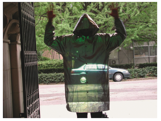
Fig. 5 Optical camouflage using RTP.
(3) Special eyewear such as shutter glasses is not necessary to observe stereo 3D images, and the observer can view the outside scenery at natural distances.
The above-described characteristics of RPT systems can be exploited to realize binocular stereovision using only one screen with an arbitrary shape. Figure 2 also shows how stereovision can be realized by using RTP. Here, the screen has an arbitrary shape covered or painted with a retroreflective material. The light projected by the right and left projectors is retroreflected from the surface of the same screen and is respectively observed by the right and left eyes. Thus, a stereoscopic view can be obtained using only one screen.
(4) Projection of multiple images on the same screen is possible, thus allowing multiple users to see their own scenery according to their viewpoints.
RPT can be used to project multiple images on the same screen; therefore, multiple users can project their own images onto the screen, and the users can view their own images independently.
The same technology can also be used to realize an autostereoscopic system with multiple viewpoints. Figure 6 shows the basic principle of the proposed RPT-based 3D display method. When images from a projector array are projected onto a retroreflector, light is strongly reflected along the direction of each projection lens. An identical number of viewpoints are created on either side of the axis of symmetry of the half mirror.
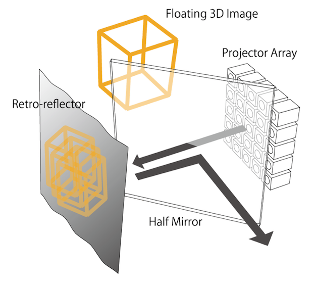
Fig. 6 Basic principle of 3D display consisting of a projector array and a retroreflector.
When a large number of projectors are arranged in a matrix, a 3D image can be viewed from multiple viewpoints. To realize smooth motion parallax, the density of projectors in the projector array must be sufficiently high. However, with commercially available projectors, it is difficult to form a projector array in which projectors are located very close to each other. One of the reasons for this is that the distance between adjacent viewpoints is limited by the size of each projector. In addition, the system scale would increase, and because of the large number of video outputs, the system cost would also increase. Therefore, a high-density projector array has been developed by arranging a number of virtual projection lenses by using a single projector and a lens array. The distance between viewpoints depends on the size of the lens array. A single video output is produced, and the cost involved is lower than that of using many individual projectors.
Figure 7 shows the optical system consisting of a high-density projector array. The system consists of a projector, a field lens, a lens array, a half mirror, and a retroreflective screen. Projected light from the projection source forms an image on the field lens. The lenses of the lens array are located at an appropriate distance so that their projected areas overlap. Each lens of the lens array works as a single projection lens. As a result, the number of lenses in the lens array is equivalent to the number of projection sources and, in turn, the number of viewpoints. Thus, the system shown in Fig. 6 is realized using a single projector in the system shown in Fig. 7.
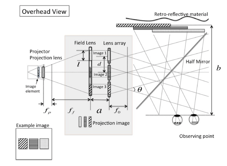
Fig. 7 Multiple viewpoint system for retroreflective projection technology.
Implementation in an actual car:
To demonstrate the effectiveness of our proposed system, a test run was carried out in which the basic system was implemented in an actual car. A retroreflector was applied to the passenger’s door and to the dashboard. In this experiment, only one camera was used and image correction based on the camera-to-subject distance was not performed. The position of the HMP was fixed and it was not worn by the operator.
Figure 8 shows the experimental result. As shown in the figure, the internal components of the car are virtually transparent, and blind spots are clearly visible. Furthermore, the displayed image was sufficiently bright in the daytime. This result qualitatively demonstrates the effectiveness of the RPT system.
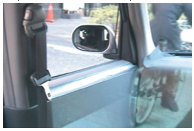
Fig. 8 Test run with Transparent Cockpit using RTP.
Implementation in Toyota Prius:
To explore the practical use of the proposed system, a setup was specifically built to fit within a Toyota Prius. The aim was to make the backseat virtually transparent, allowing the driver to see otherwise blind spots at the rear when reversing the car (Figure 9). In this application, the system had six viewpoints.
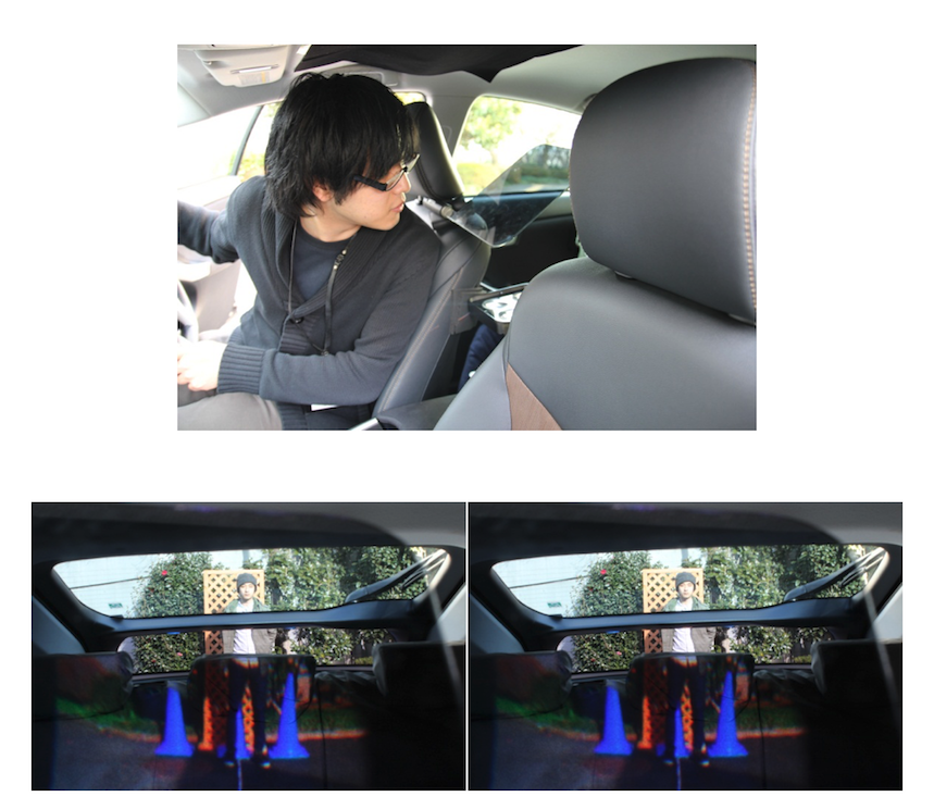
Fig. 9 (Above) The driver was able to see images (Bottom) that were captured by the cameras behind the car.
CONCLUSION
A Transparent Cockpit can change our experience of driving a car or of traveling in other means of transportation such as trains and airplanes. A Transport Cockpit aims to convey the feeling of “floating” in the vehicle as opposed to riding it. As such, a Transparent Cockpit is a type of augmented reality application, which can be used to enhance our ability to perceive the world around us.
References
[Tachi, 1999] Susumu Tachi: Augmented Telexistence, in Y. Ohta and H. Tamura (eds.), Mixed Reality - Merging Real and Virtual Worlds, Springer-Verlag, ISBN3-540-65623-5, pp. 251-260, 1999.
[Inami et al., 2000] Masahiko Inami, Naoki Kawakami, Dairoku Sekiguchi, Yasuyuki Yanagida, Taro Maeda, and Susumu Tachi: Visuo-Haptic Display Using Head-Mounted Projector, Proceedings of IEEE Virtual Reality 2000, New Brunswick, New Jersey, USA, pp. 233-240 (2000.3) [PDF]
[Tachi, 2003] Susumu Tachi: Telexistence and Retro-reflective Projection Technology (RPT), Proceedings of the 5th Virtual Reality Internationl Conference (VRIC2003), pp. 69/1-69/9, Laval Virtual, France (2003.5) (Invited Keynote Paper) [PDF]
[Yoshida et al., 2007] Takumi Yoshida, Kouta Minamizawa, Kensei Jo, Hideaki Nii, Naoki Kawakami and Susumu Tachi: Transparent Cockpit, 34th Int. Conf. On Computer Graphics and Interactive Techniques (ACM SIGGRAPH 2007), Emerging Technologies, San Diego, USA (2007.8) [PDF]
[Yoshida et al., 2013] Takumi Yoshida, Keitaro Shimizu, Tadatoshi Kurogi, Sho Kamuro, Kouta Minamizawa, Hideaki Nii and Susumu Tachi: RePro3D: Full-parallax 3D Display with Haptic Feedback using Retro-reflective Projection Technology, Proceedings of International Symposium on Virtual Reality Innovations (ISVRI 2011), Singapore, pp.49-54 (2011. 3) [PDF]
[Tachi et al., 2014] Susumu Tachi, Masahiko Inami and Yuji Uema: The Transparent Cockpit, IEEE Spectrum, vol.51, no.11, pp.52-56 (2014.11).