| Principle of Retroreflective Projection Technology | RPT-Based Head-Mounted Projector |
| RPT Applications | References |
The ability to enhance our perception of the world around us has long been a human dream, and augmented reality (AR) is now bringing it within reach. This multidisciplinary field aims to seamlessly integrate digital information into real-world environments. Susumu Tachi and his team proposed and developed retroreflective projection technology (RPT), an elegant and cost-effective approach that can turn almost any real object into a strikingly lifelike visual display. Retroreflective materials return light toward its source, enabling versatile optical systems that support stereoscopic vision and accurate occlusion. Because the projection surface can be any shape, one practical application known as “Optical Camouflage” projects a background image onto an opaque object—such as a vehicle or an overcoat—so that it appears invisible, a concept once confined to science fiction.
This technology can be applied in many settings. For example, in a cockpit, the aircraft floor could be made virtually transparent during landing, allowing the pilot to see the runway directly and land more safely. Similarly, RPT could help eliminate the notorious blind spots of trucks and automobiles. It could also provide an outside view in windowless rooms by making a wall appear transparent. In medicine, pre-acquired X-ray and/or MRI data can be superimposed on a patient’s body, giving surgeons essential information for open procedures as well as minimally invasive surgery. By superimposing ultrasound data, RPT can also provide a real-time view of internal structures.
This technique grew out of research aimed at achieving the seamless integration of digital information into real-world environments to improve safety, boost productivity, and enhance human perception.
| Principle of Retroreflective Projection Technology | RPT-Based Head-Mounted Projector |
| RPT Applications | References |
Principle of Retroreflective Projection Technology
Two classic visual display types for virtual reality are the Head-Mounted Display (HMD) (Sutherland, 1968; Fisher et al., 1986) and Immersive Projection Technology (IPT) (Cruz-Neira et al., 1993). Although both are useful, they have shortcomings, as shown in Figs. 1(c) and 1(d), respectively. HMDs involve a trade-off between high resolution and a wide field of view, whereas IPT systems can suffer from shadows cast by the user’s body and from difficulties in integrating the user’s real body with the virtual interface. In addition, both approaches face occlusion problems under augmented-reality conditions (i.e., when virtual and real objects are combined).
Fig. 1(a) shows a virtual vase and a virtual ashtray on a virtual desk. When a real hand is placed between two virtual objects, occlusion should ideally occur as shown in Fig. 1(b): the real hand occludes the virtual vase while being occluded by the virtual ashtray at the same time. However, with an optical see-through HMD, the real hand cannot occlude the virtual vase and cannot be occluded by the virtual ashtray; consequently, both the hand and the ashtray appear transparent. This occurs because the physical display of an HMD is always located just in front of the user’s eyes.
Conversely, in IPT implementations such as CAVE (Cave Automatic Virtual Environment), the virtual ashtray cannot occlude a real hand, as shown in Fig. 1(d). This is because virtual objects are rendered on the screen surface, which in IPT displays is typically one to two meters away from the user.
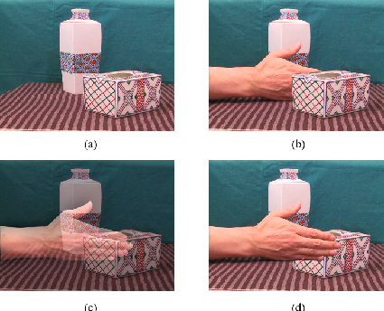
Fig. 1. (a) A virtual vase and a virtual ashtray on a virtual desk. (b) Ideal occlusion when a real hand is placed between two virtual objects. (c) Unfavorable results with an optical see-through HMD. (d) Unfavorable results with IPT (Immersive Projection Technology) implementations such as CAVE.
A new type of visual display is currently being developed under the names “media X’tal” (pronounced “crystal”) (Kawakami et al., 1998) and “X’tal vision” (Inami et al., 1999, 2000). This approach uses retroreflective materials as the projection surface and is collectively referred to as RPT (Tachi, 1999, 2003).
Under the RPT configuration, a projector is placed at a position axially symmetric to the user’s eye (using a half mirror as a reference), and a pinhole is placed in front of the projector to ensure sufficient depth of field, as shown in Fig. 2. This setup is referred to as the “conjugate optical condition” and forms the basis of RPT. Images are projected onto a screen that is constructed, painted, or covered with a retroreflective material.
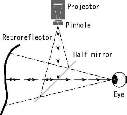
Fig. 2. Principle of the RPT system.
Conventional screens used in IPT scatter projected light in all directions, like a Lambertian surface. In contrast, retroreflective surfaces return most of the projected light toward the projector (Fig. 3).
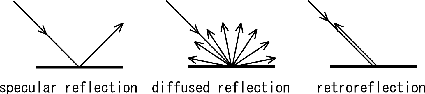
Fig. 3. Three typical reflection patterns.
Fig. 4 shows the behavior of a retroreflective surface. It is covered with microscopic beads about 50 micrometers in diameter, which return incident light toward its source. The same effect can also be achieved using prism-shaped retroreflectors densely distributed across the surface.
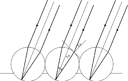
Fig. 4. Retroreflective surface densely covered with microscopic beads about 50 micrometers in diameter. Ideally, the refractive index should be 2.
The retroreflector screen, together with the pinhole, ensures that the user always sees images with correct occlusion relationships. Screens of arbitrary shape can be used in RPT systems due to the properties of retroreflectors and the presence of a pinhole in the conjugate optical system.
Using these characteristics, binocular stereovision becomes possible with a single screen of arbitrary shape. Fig. 5 shows how stereovision can be realized using RPT. In Fig. 5, the display unit is an arbitrarily shaped object covered or painted with a retroreflective material. Light projected by the right projector is retroreflected from the display unit and observed by the right eye, while light projected by the left projector is retroreflected by the same surface and observed only by the left eye.
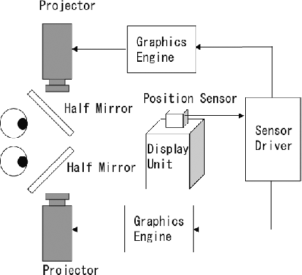
Fig. 5. Principle of a stereo display based on RPT.
Using the same display surface, the right eye sees the image projected by the right projector and the left eye sees the image projected by the left projector. By generating CG images with appropriate binocular disparity, the observer perceives a stereoscopic view at the display unit’s location. Using measurements from a position sensor on the display unit, the system can update the rendered 3D image according to the unit’s position and orientation, giving the user the sensation of handling a real object.
The same technology can be used by multiple users to observe the same screen. Simultaneous multi-projection onto the same surface is possible: each user projects their own image while still being able to see it independently. This feature can be used, for instance, to project multiple images onto the same robot, as in mutual telexistence (Tachi, 2003; Tachi et al., 2008).
| Principle of Retroreflective Projection Technology | RPT-Based Head-Mounted Projector |
| RPT Applications | References |
RPT-Based Head-Mounted Projector
An RPT-based Head-Mounted Projector (HMP) can be worn on a user’s head. Fig. 6 illustrates the implementation of RPT on an HMP, and Fig. 7 shows a prototype. Although an RPT-based HMP can project bright, high-contrast stereoscopic color images onto a free-form screen surface, the large half mirror covers most of the wearer’s face.
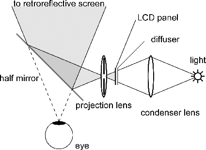
Fig. 6. Principle of the original RPT-based HMP (Head-Mounted Projector).
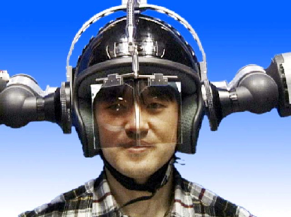
Fig. 7. General appearance of a Head-Mounted Projector (HMP).
To address this issue, the X’tal Visor was developed as a fully open-type RPT-based HMP (Sonoda et al., 2005). The X’tal Visor replaces the half mirror with an all-reflective micromirror positioned near the focal point of the projection lens, allowing the required mirror size to be extremely small. Because the micromirror is placed very close to the user’s eye, the conjugate optical condition necessary for RPT can be achieved without a half mirror. Fig. 8 illustrates the principle of an HMP using a micromirror.
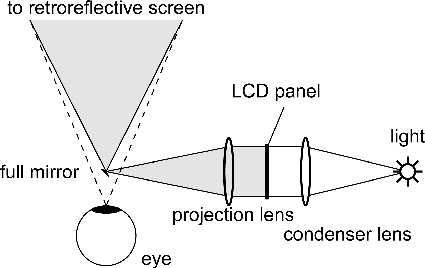
Fig. 8. Principle of a fully open-type HMP based on RPT.
Because the mirror is smaller than the user’s pupil, it does not obstruct their field of view. The X’tal Visor can display images without covering the wearer’s face, enabling natural face-to-face communication. In addition, a spherical mirror can be used to achieve a wider projection field. Because a spherical mirror distorts the projected image, the image on the LCD must be pre-warped to produce an undistorted image on the screen. Fig. 9 shows an implementation of the X’tal Visor.
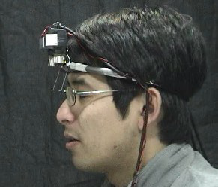
Fig. 9. General view of the X’tal Visor.
| Principle of Retroreflective Projection Technology | RPT-Based Head-Mounted Projector |
| RPT Applications | References |
RPT Applications
Fig. 10 shows an example of an image projected onto a person wearing a shirt covered with a retroreflective sheet. As shown in the figure, the projected image resembles a real skeleton, and it is partly occluded by the fingers of the person wearing the retroreflective material.
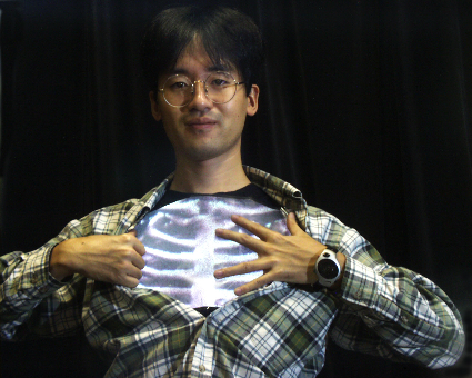
Fig. 10. Image projected onto a retroreflective screen.
This is an example of an augmented-reality application of RPT. Pre-acquired X-ray and/or MRI data can be superimposed on a patient to provide surgeons with essential information for open procedures as well as minimally invasive surgery. By superimposing ultrasound data, a real-time representation of internal structures is also possible through RPT.
Fig. 11 shows an example in which a virtual cylinder is projected onto a Shape Approximation Device (SAD), a haptic device (Tachi et al., 1994; Hoshino and Tachi, 1998) that allows the user to experience realistic tactile sensations when touching virtual objects. Using the SAD as a retroreflective screen enables the user to perceive the object as though viewing it through an HMP. Fig. 11(a) illustrates the principle of the SAD, Fig. 11(b) shows the displayed image, Fig. 11(c) shows the actual device, and Fig. 11(d) shows the image projected onto the SAD, in which tactile information corresponding to the object’s shape can be perceived correctly.
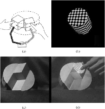
Fig. 11. Image projected onto a Shape Approximation Device (SAD). (a) Principle of the AED (Active Environment Display) based on the SAD. (b) Displayed image. (c) Actual SAD device. (d) Image projected onto the SAD, in which tactile information corresponding to the shape of the object can be perceived correctly.
Fig. 12 shows an example of an RPT-based augmented-reality interface for medical applications, in which relevant visual information is projected directly onto the working area to support the user.
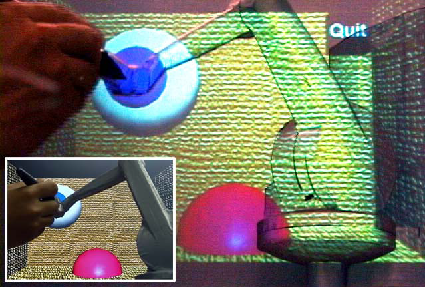
Fig. 12. An example of an application of RPT in medicine.
Fig. 13 shows how “Optical Camouflage” can be achieved using real-time video information. Fig. 14 shows an RPT system that realizes the situation shown in Fig. 13. The coat is made of a retroreflective material so that light is reflected back toward its source.
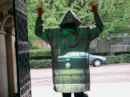
Fig. 13. Optical Camouflage using RPT.
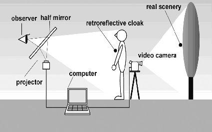
Fig. 14. Schematic diagram of the RPT system used for Optical Camouflage in Fig. 13.
Microscopic beads on the surface of the coat provide retroreflection, as described earlier. A half mirror allows observers to view the scene from a virtual viewpoint near the projector. An HMP projects an image of the background scenery captured by the video camera behind the camouflaged person. A computer uses image-based rendering techniques to calculate the appropriate perspective and transform the captured image into the one projected onto the subject. Because the cloak is made of retroreflective material that returns incident light toward its source, an observer looking through the half mirror sees a very bright image of the scenery behind the camouflaged person, making the wearer appear virtually transparent.
Another application is the “transparent cockpit,” as shown for a passenger car in Fig. 15. For safety and usability, it is important to maintain a wide field of view while operating a vehicle, but the window area is limited. In a transparent cockpit, images of objects located in blind spots are displayed on the inner surfaces of the vehicle using RPT, making structural elements such as doors and the floor appear transparent. As a result, blind spots are reduced and objects that would otherwise be occluded can be seen as if through a window (Yoshida et al., 2008). This technology can also be applied to helicopters or airplanes by making the floor virtually transparent to assist pilots during landing.
Thus, RPT provides a way to transform almost any physical object into a virtual display simply by covering its surface with a retroreflective material.
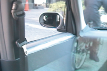
Fig. 15. Transparent cockpit of a passenger car.
| Principle of Retroreflective Projection Technology | RPT-Based Head-Mounted Projector |
| RPT Applications | References |
References
- Cruz-Neira, C., Sandin, D. J. and DeFanti, T. A. (1993). Surrounded-screen projection-based virtual reality: The design and implementation of the CAVE. Proceedings of the ACM SIGGRAPH’93, pp. 135–142.
- Fisher, S. S., McGreevy, M., Humphries, J. and Robinett, W. (1986). Virtual environment display system, Proceedings of the ACM 1986 Workshop on Interactive 3D Graphics, Chapel Hill, NC, October 1986, pp. 77–87.
- Hoshino, H. and Tachi, S. (1998). A method to represent an arbitrary surface in an encounter-type shape representation system, Proceedings of the 7th IEEE International Workshop on Robot and Human Communication (RO-MAN ’98), Takamatsu, Japan, pp. 107–114.
- Inami, M., Kawakami, N., Sekiguchi, D., Yanagida, Y., Maeda, T., Mabuchi, K. and Tachi, S. (1999). Head-mounted projector, ACM SIGGRAPH’99 Conference Abstracts and Applications (Emerging Technologies), p. 179.
- Inami, M., Kawakami, N., Sekiguchi, D., Yanagida, Y., Maeda, T. and Tachi, S. (2000). Visuo-haptic display using head-mounted projector, Proceedings of the IEEE Virtual Reality 2000, New Brunswick, New Jersey, USA, pp. 233–240.
- Kawakami, N., Inami, M., Maeda, T. and Tachi, S. (1998). Media X’tal — Projecting virtual environments on ubiquitous object-oriented retroreflective screens in the real environment, SIGGRAPH’98, Orlando, Florida, USA.
- Sonoda, T., Endo, T., Suzuki, Y., Kawakami, N. and Tachi, S. (2005). X’tal Visor, ACM SIGGRAPH 2005 (Emerging Technologies).
- Sutherland, I. E. (1968). A head-mounted three-dimensional display, Proceedings of the Fall Joint Computer Conference, pp. 757–764.
- Tachi, S., Maeda, T., Hirata, R. and Hoshino, H. (1994). A construction method of virtual haptic space, Proceedings of the 4th International Conference on Artificial Reality and Tele-Existence (ICAT ’94), Tokyo, Japan, July 1994, pp. 131–138.
- Tachi, S. (1999). Augmented telexistence, in Mixed Reality, Tamura and Ohta (eds.), Springer-Verlag, pp. 251–260.
- Tachi, S. (2003). Telexistence and retroreflective projection technology (RPT), Proceedings of the 5th Virtual Reality International Conference (IVRIC2003), Laval Virtual, France, pp. 69/1–69/9.
- Tachi, S., Kawakami, N., Nii, H., Watanabe, K. and Minamizawa, K. (2008). TELEsarPHONE: Mutual telexistence master–slave communication system based on retroreflective projection technology, SICE Journal of Control, Measurement, and System Integration, Vol. 1, No. 5, pp. 1–10.
- Yoshida, T., Jo, K., Minamizawa, K., Nii, H., Kawakami, N. and Tachi, S. (2008). Transparent cockpit: Visual assistance system for vehicle using retroreflective projection technology, Proceedings of the IEEE Virtual Reality 2008, Reno, USA, pp. 185–188.