-Invention and development of an intelligent mobile robot system for the blind called Guide Dog Robot (1976-1983) known as MELDOG, which is the first of its kind-
| SUMMARY | DETAILS | INTRODUCTION | GUIDE DOG ROBOT | NAVIGATION | COMMUNICATION |
| CONCLUSIONS | Research Episodes and Circumstances | REFERENCES |
SUMMARY
The Guide Dog Robot Project started in the 1977 fiscal year at MEL (Mechanical Engineering Laboratory, Ministry of International Trade and Industry). The project's goal is to enhance mobility aids for the blind by providing them with the functions of guide dogs, i.e., obedience in navigating or guiding a blind master, intelligent disobedience in detecting and avoiding obstacles in his/her path, and well-organized human-machine communication which does not interfere with his/her remaining senses. In this paper, the design concept of the Guide Dog Robot MELDOG is described first. Next, the navigation method using an organized map and landmarks, obstacle detection/avoidance system based on the ultrasonic environment measurement and man-machine communication via electrocutaneous stimulation system are presented. The results of the feasibility studies using MELDOG MARK I, II, III and IV test hardwares are discussed. Future problems are also elucidated.
| SUMMARY | DETAILS | INTRODUCTION | GUIDE DOG ROBOT | NAVIGATION | COMMUNICATION |
| CONCLUSIONS | Research Episodes and Circumstances | REFERENCES |
DETAILS
From Susumu Tachi and Kiyoshi Komoriya: Guide Dog Robot, in M.Brady et al.ed., The Robotics Research 2 (The Second International Symposium 1984), MIT Press, pp.333-349 (1985) [PDF]
| SUMMARY | DETAILS | INTRODUCTION | GUIDE DOG ROBOT | NAVIGATION | COMMUNICATION |
| CONCLUSIONS | Research Episodes and Circumstances | REFERENCES |
INTRODUCTION
Independent travel is one of the strongest desires of about three hundred thousand blind or severely visually impaired individuals in Japan. Since the concept of technological assistance for the blind is of recent origin (after World War II), they have been largely on their own, depending upon more sensitive and subtle utilization of their remaining senses, and extending them through the use of the cane, or relying upon human or dog guides,
Ideal mobility aids for the blind should support the three necessary functions for mobility; i.e.,
(1)the blind person's next step, (2) his/her directional orientation, and (3) his/her navigation along reasonably long travel path on both familiar and unfamiliar terrain [Mann, 1974]. However, existing mobility devices; e.g., the Pathsounder [Russell, 1971], the Sonic Glasses [Kay, 1973], the Laser Cane [Farmer et al., 1975], the Mowat Sensor [Morrissette et al., 1981] and the Nottingham Obstacle Detector [Dodds et al., 1981], have only functions (1) and (2). The information processing system employed by the existing devices is very simple and crude so that the blind user must concentrate on the devices, resulting in the fatigue of the user or loss of other information which otherwise might be obtained through the remaining senses.
It is quite desirable to design more intelligent mobility aids for the blind which combine the above three functions with the enhancement of functions (1) and (2) by increasing the information processed by the device or the machine. These devices should warn only if the blind persons are in danger, thereby not distracting the attention of the blind traveler from other potential cues through their remaining senses. This design concept is very similar to traveling with a guide dog (Seeing-eye).
The purpose of the Guide Dog Robot Project (dubbed MELDOG) which started in 1977 is to enhance mobility aids for the blind by providing them with the functions of guide dogs; i.e., obedience in navigating a blind master, intelligent disobedience in detecting and avoiding obstacles in his/her path, and well-organized man-machine communication which does not interfere with his/her remaining senses.
In this paper the design concept of MELDOG is first described. Next, the navigation using an organized map and landmarks, obstacle detection/avoidance system based on the ultrasonic environment measurement and human-machine communication via an electrocutaneous stimulation system are presented. While theoretical consideration has been done for the realization of these functions by machines, feasibility studies of the proposed methods have been conducted both by computer simulation and field tests using the test hardwares.
The results of the feasibility experiments using MELDOG MARK I, II, III and IV test hardwares are discussed and the future problems are elucidated.
| SUMMARY | DETAILS | INTRODUCTION | GUIDE DOG ROBOT | NAVIGATION | COMMUNICATION |
| CONCLUSIONS | Research Episodes and Circumstances | REFERENCES |
GUIDE DOG ROBOT
In order to realize a robot that can assist a blind master's mobility, the following three fundamental control and communication problems of human-machine systems must be solved,
(a) How a robot guides itself by using an organized map of the environment and registered landmarks in the environment.
(b) How the robot finds obstacles which are not registered on the map and avoids them,
(c) How the robot informs its blind master about the route and the obstacles detected.
Two main functions of real guide dogs are obedience and intelligent disobedience, which corresponds to the navigation and obstacle detection, respectively. Adding to these communication between the blind master and the dog is necessary. In order to realize these main functions by solving the above three problems we have set the following specifications for the guide dog robot:
(1) In principle, the master takes the initiative. The master commands the robot by control switches connected by a wired link. The robot precedes the master and stops at each intersection, waits for the master's next order (right, left, straight, or stop) and obeys it. If the master does not know the area and wants full automatic guidance, all he has to do is assign the starting code and the destination code. The robot determines whether there is a route to the destination. If more than one route exists, it chooses the optimal route and guides the master accordingly. The robot stops at each intersection as a safety precaution (See Landmark Sensor Subsystem of Fig. 1).
(2) When the robot detects a dangerous situation on the road, it no longer obeys the master's command but gives him a warning. If the obstacle is moving toward the master, it stops and alerts the moving object and the master. If the obstacle is moving in the same direction but slower than the master, it asks the master to reduce his/her speed to follow the preceding object, probably a human traveler. If something is crossing in front of the robot, the robot waits till it passes. If it detects an obstacle which does not move, it tries to determine if it is possible to find space that will permit the safe transport of the master around the obstacle. If space exists, it safely guides the master around the obstacle. If not, it tries to find a new route to the destination without using an undesirable path (See Obstacle Detection Subsystem of Fig. 1).
(3) In general, the speed of the robot is controlled so that it coincides with that of the blind master's gait. Thus, if the master walks slowly or rapidly, the robot moves accordingly, keeping the distance between them almost constant. As long as the master is considered to be safe by the robot he is not warned, so that he or she may concentrate on his/her remaining senses and his/her own decisions. Only when he or she fails to detect an obstacle or is out of the safety zones, is he or she warned by the robot (See Man-Machine Communication Subsystem of Fig. 1).
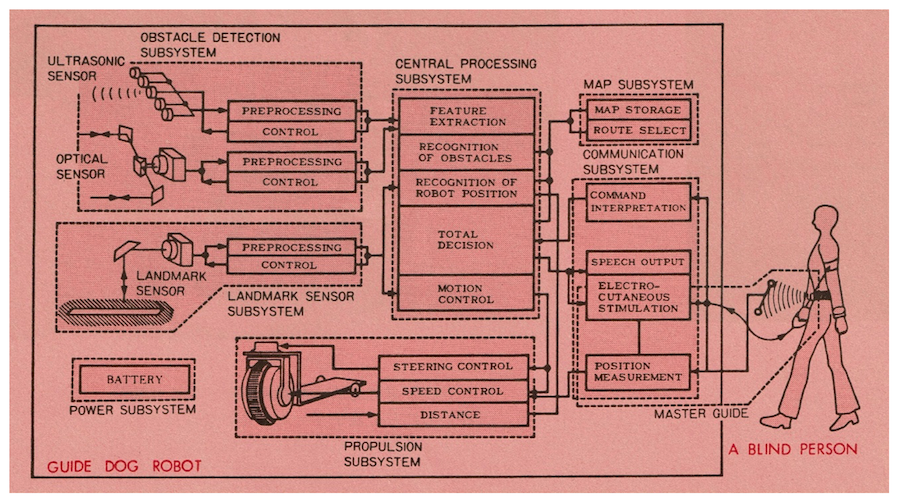
Fig. 1 Schematic diagram of the guide dog robot system (MELDOG).
| SUMMARY | DETAILS | INTRODUCTION | GUIDE DOG ROBOT | NAVIGATION | COMMUNICATION |
| CONCLUSIONS | Research Episodes and Circumstances | REFERENCES |
NAVIGATION
The fundamental data base of the robot is its navigation map stored in the auxiliary memory; e.g., cassette tapes, and transferred into the main memory of the robot when in use. The navigation map consists of information about intersections, i.e., names and types of intersections, distance between two adjacent intersections, and orientation to the adjacent intersections. Information on the landmarks to identify the intersections and other essential points of navigation are also included in the navigation map. This map is represented as an automaton as shown in Fig. 2.
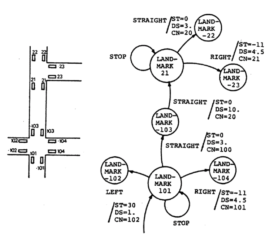
Fig. 2 An example of the landmarks and the automaton representation of the navigation map.
The next step the robot should take is to identify the real intersection as specified on the map and correct its position and orientation so that it can travel farther. In order to do so, specific landmarks are chosen for each intersection or other essential points of navigation. In the initial phase (from 1977 to 1982) white painted lines on the streets with a length of about 2m and a width of 0.15m were adopted as the landmarks. These marks had to be set at every crossing at this stage of development. The automaton representation map for the robot could be automatically produced by an off-line computer from an ordinary map using picture processing techniques. Landmark laying instructions which would be used to place the landmarks on the streets could be provided at the same time [Kaneko et al., 1983].
At the second stage (from 1983 to the present) registered natural landmarks such as poles and walls are being used as markers for the correction of the robot's position and orientation. However, the navigation method is fundamentally the same.
Navigation Map
Figure 2 shows an example of landmarks set on the streets and the automaton representation of the map of landmarks in the memory. Landmark codes which contain information on intersection identification number, intersection type, i.e., crossings, forked roads, straight roads, etc., and stop information, i.e., it should stop at the landmark or not, correspond to the states of the automaton. Commands from the blind traveler (or Central Processing Subsystem (CPS) in automatic guidance mode) such as turn to the left, right, or go straight correspond to the input of the automaton, while information to the CPS and/or the blind master such as the steering angle to be used to reach the next landmark, the distance between two landmarks, and intersection attributes correspond to the automaton outputs.
The same map can be interpreted as the treestructure shown in Fig. 3. In this representation landmark codes correspond to the nodes of the tree and commands from the user correspond to the branches. Each branch has an attribute represented as the output in the automaton representation. If the user assigns a starting landmark code and a destination code, the robot can find whether there is a route to reach the destination or not, by using the tree-structure representation of the map and searching techniques commonly used in artificial intelligence study, and can find an optimal route if plural routes exist.
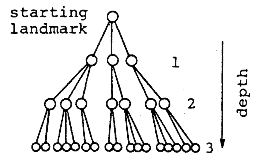
Fig. 3 Tree-structure representation of the navigation map.
Once an optimal route is determined the robot can determine the command sequence such as turn to the left, go 30 m, then turn to the right etc., by following the tree-structure. This sequence is used as the input sequence to the aforementioned automaton, resulting in the fully automatic guidance of the traveler. Photo 1 shows a general view of the outdoor experiments of the test MELDOG MARK II using landmarks and the navigation map.
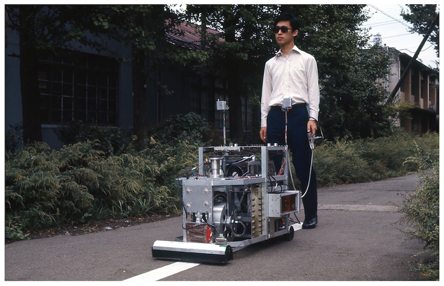
Photo. 1 Navigation experiment with MELDOG MARK II using landmarks and navigation map.
Figure 4 shows an example of the navigation map and some results of the route search. In the figure, s indicates the total length of the route in meters. In this example the area is 500 m x 500 m with 276 landmarks, which requires 2 K byte memories.
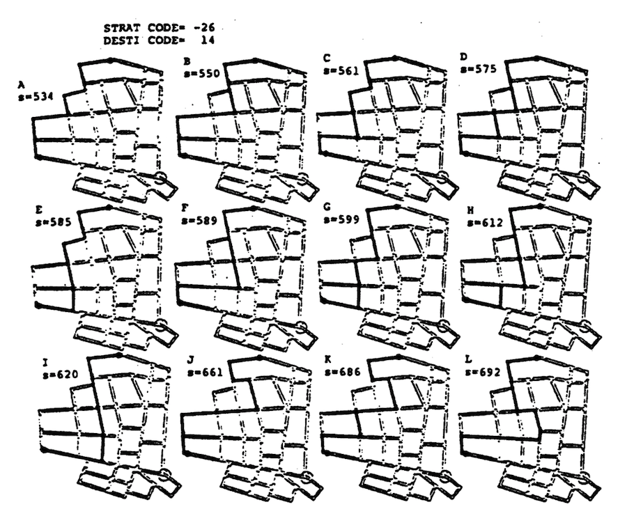
Fig. 4 Results of the route search.
The search area of the optimal route can be extended by connecting the above sub-maps. Figure 5 shows an example of an extended map. By applying the dynamic programming method an optimal route can be found that minimizes the total length of the route. Any criteria can be chosen arbitrarily, e.g., the total length of the route, minimum number of intersections encountered, etc., or a combination of these [Tachi et al., 1980].
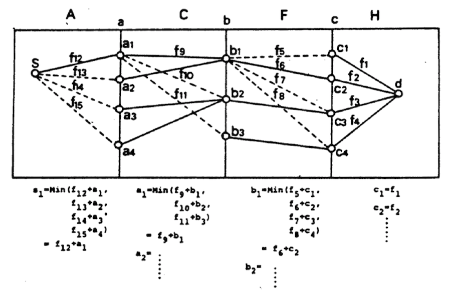
Fig. 5 Optimal route searching by connecting sub-maps.
Navigation between Landmarks
The robot travels from one landmark to another using landmark information in the navigation map to generate a desirable path.
Figure 6 shows an example of path generation when the starting vector and the destination vector are assigned. The designed path, which connects the current position with an arbitrary intermediate destination, consists of two arcs and their common tangent. After determining a path the robot travels along it using the encoders of the steering shaft and the rear wheels. Each arrow of Fig.6 indicates the final experimental position of the robot after following the path. In the figure, b) and c) show better navigation results through controlled steering compensation [Komoriya et al., 1984].
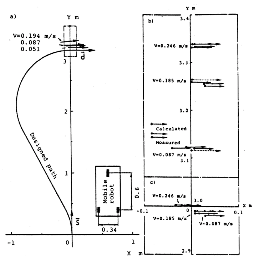
Fig. 6 Path generation and the result of the path following experiments.
In navigation using internal sensors, accumulation of error from a course is inevitable. In order to guide the robot along the path accurately it is necessary to compensate for this. Three methods are studied to solve this problem.
i) landmark tracking method
In the first method landmarks are used to compensate for course error. When the robot reaches a landmark, it adjusts its orientation and position by moving along the landmark (See Fig.7). The robot has two landmark sensors, one at its front and one at its rear end, which optically detect landmark edges. After lateral course error  and orientational error
  are measured, equation (1) gives the steering angle
  which enables the robot to follow the landmark [Komoriya et al., 1983, Tachi et al., 1980).

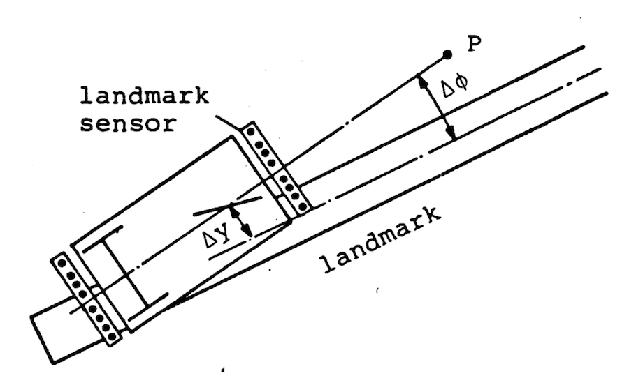
Fig. 7 Landmark tracking method.
ii) Utilization of road edges
A landmark tracking method is effective if the deviation from the course can be within the detection area of landmark sensors when the robot reaches a landmark. This condition restricts the distance between landmarks. Using the road edges as an auxiliary method, supports landmark tracking, and enables the distance between landmarks to be longer.
Figure 8 shows a general view of this method. The robot detects the road edge, shown as the x-coordinate axis, from the points where the road edge crosses the CCD camera's field of view by processing the visual data using the road edge attributes of the navigation map. After calculating  robot's orientation to the road edge, and
  distance from its course by equations (2), the steering angle is given by equation (3).
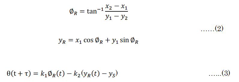
where  is sampling time.
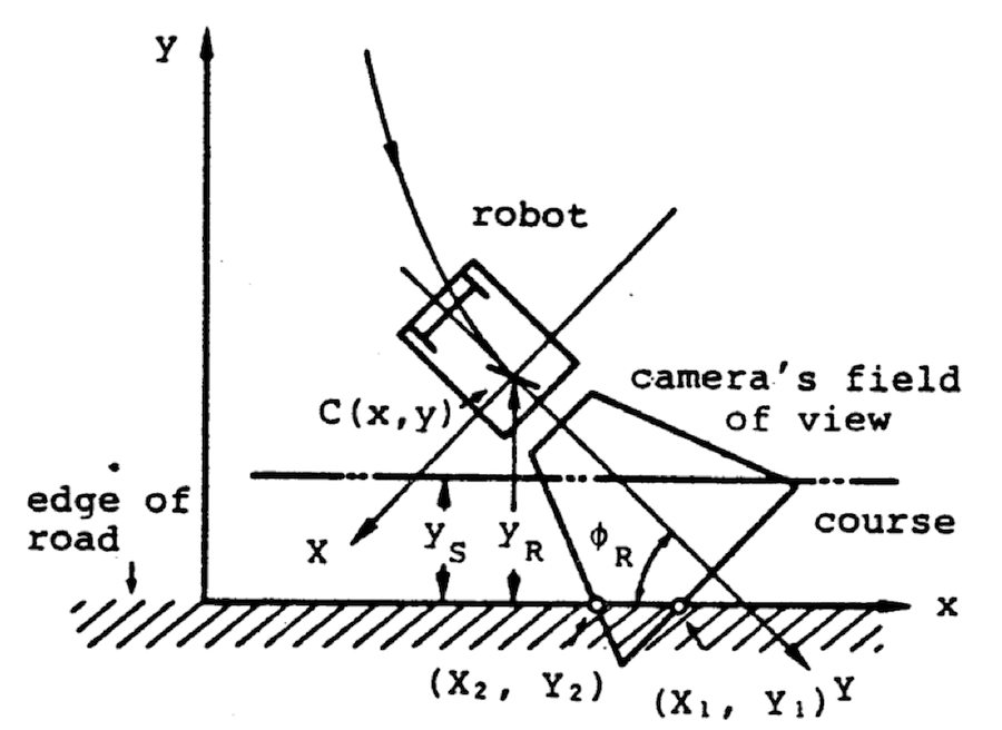
Fig. 8 Utilization of road edges.
Photo. 2 shows the CCD camera assembled for this purpose and installed on MELDOG MARK IIb. Its field of view can be changed to the front, right and left side of the robot by turning the table which supports the camera and far and nearby tilting the mirror which alters the vision line, One micro-computer is mounted on board the robot to control these operation and to process visual data exclusively [Tachi et al,, 1982 a].
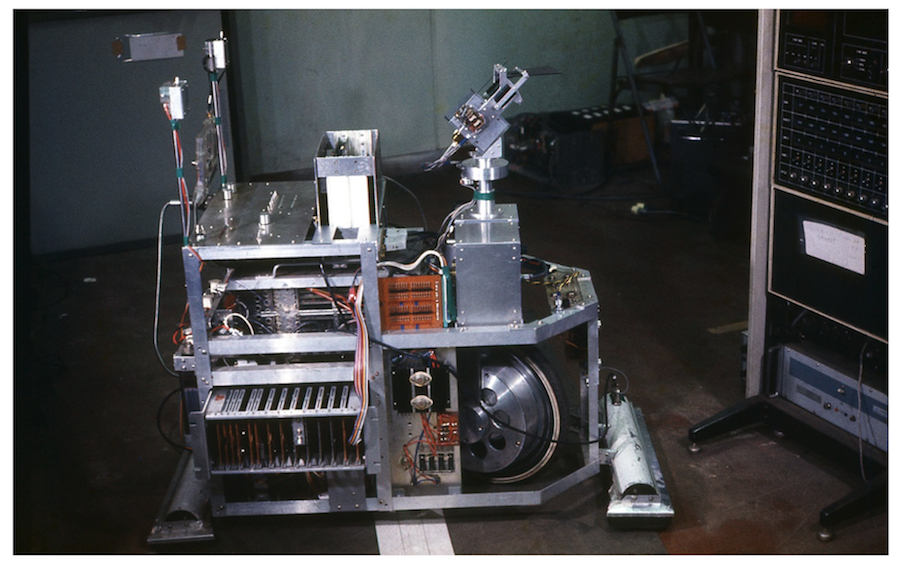
Photo. 2 MELDOG MARK IIb with CCD visual sensor for detection of road edge.
iii) Utilization of natural landmarks
Instead of artificial landmarks such as painted lines, natural landmarks such as poles and walls which have rather simple shapes so that the sensor on board the robot can measure their position .easily are more desirable for navigation.
From the view point of signal processing in real-time, ultrasonic sensors are preferable. The construction of the ultrasonic sensor used here and the position measurement algorithm is described in the next section.
Landmark position using this kind of ultrasonic sensor is measured as shown in Fig, 9, In this figure the robot is assumed to move along the x axis and to measure the position of a cylinder-like shaped object from the plural points Pi, In order to increase accuracy, only distance data is used, Using the radius of the object, relative position of the object ( ,
,  ) can be calculated by equations (4). However, this information is not sufficient to decide the absolute position of the robot because of the lack of directional data.
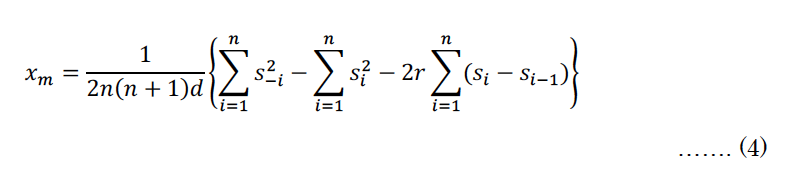
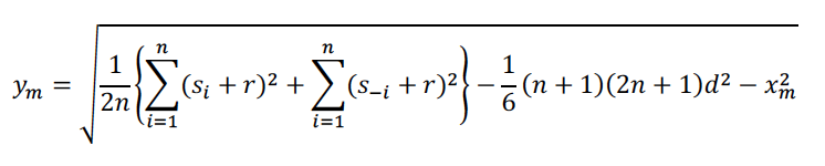
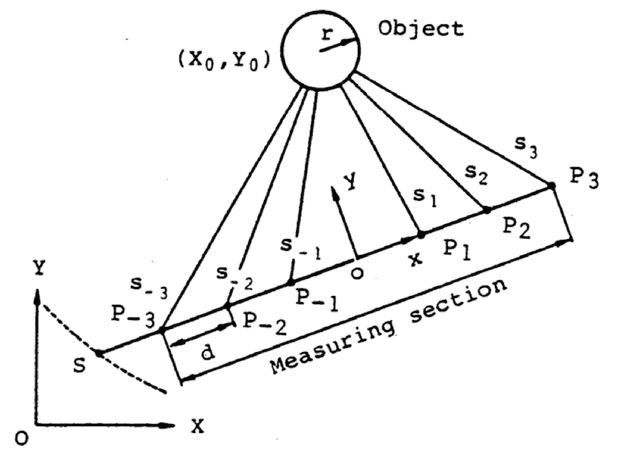
Fig. 9 A method to measure an object as a landmark.
Among several methods to solve this problem such as utilization of a rate gyro sensor and two landmarks at one time, the use of flat surfaces such as walls is practical if the navigation is inside buildings. Photo. 3 shows the test hardware MELDOG MARK IV which has this ability to use walls as landmarks and with ultrasonic sensors at both sides of its body [Komoriya et al., 1984].
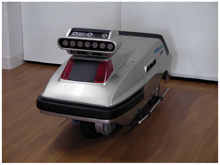
Photo. 3 MELDOG MARK IV used to demonstrate the navigation using walls as landmarks.
Obstacle Detection
It is important for the robot to find various obstacles while it guides the master, which appear in front of it, such as obstacles which block its path, objects and humans that come toward the robot and the master, steps or uneven streets, overhanging objects like awnings, etc.
In order to detect these obstacles, an ultrasonic sensor, which can determine not only the distance from the obstacle but also its direction by the traveling time measurement of ultrasound was developed.
Fig.10. shows its construction with one transmitter and plural receivers arranged in an array d distance apart from each other. A tone burst of frequency 40kHz and duration time 25msec is sent by the transmitter. Each of the receivers detects the reflected signal by obstacles ti seconds later from the transmission, which corresponds to the distance Si from T to Ri through the obstacle surface. Detected signals are amplified, processed by band-pass-filters and compared with the appropriate threshold so as to make stop-pulses for the counters which measure ti in order to get the aforementioned Si.
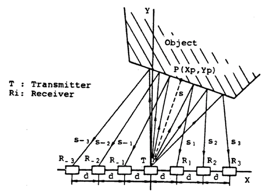
Fig. 10 Construction of ultrasonic sensor.
Location of the object can be calculated from Si by equations (5), which assumes that the ultrasound is reflected at a flat surface as shown in the figure. According to the numerical calculation this algorithm gives almost correct position and direction with less than two percent error if the obstacle has a cylindrical surface or is a circle in a two dimensional figure [Komoriya et al., 1984].
When the robot detects an object in its sensing area, it can determine the relative speed V of the object by measuring distance at more than two instances. If V is positive, it means that the object is moving away from the robot and it will not bother the robot. Therefore the robot needs not take any action.
If V is negative, the robot behaves as follows. If the absolute value of V is larger than the speed of the robot Vr, i.e. the object is coming towards the robot, the robot quickly stops and warns the master and the object in order to avoid a collision.
If the absolute value of V is smaller than Vr, i.e. the object is moving in the same direction of the robot and the master at a slower speed, the robot asks the master to slow down and tries to follow the object keeping a safe distance between them (See Photo.4).
If the absolute value of V is equal to Vr, i.e. the object is standing still, the robot modifies its path to avoid the obstacle. Fig.11 shows the path to avoid an obstacle in front of it. At the time the robot detects a stationary obstacle, it generates a path with maximum space between the obstacle and the robot as shown by the dotted line.
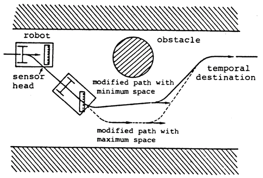
Fig. 11 Example showing the avoidance of an obstacle by modifying the robot's path.
While it moves along this modified path, the ultrasonic sensor continues to detect obstacles along the road by turning the sensor head. If the obstacle leaves the detection area of the sensor and the robot has open space in front of it, the robot generates its path again to return to the initial path with minimum space as shown by the solid line after avoiding the obstacle.
When the robot does not have open space along the path with maximum space, i.e. the road is blocked, the robot turns back generating a new path to its final destination.
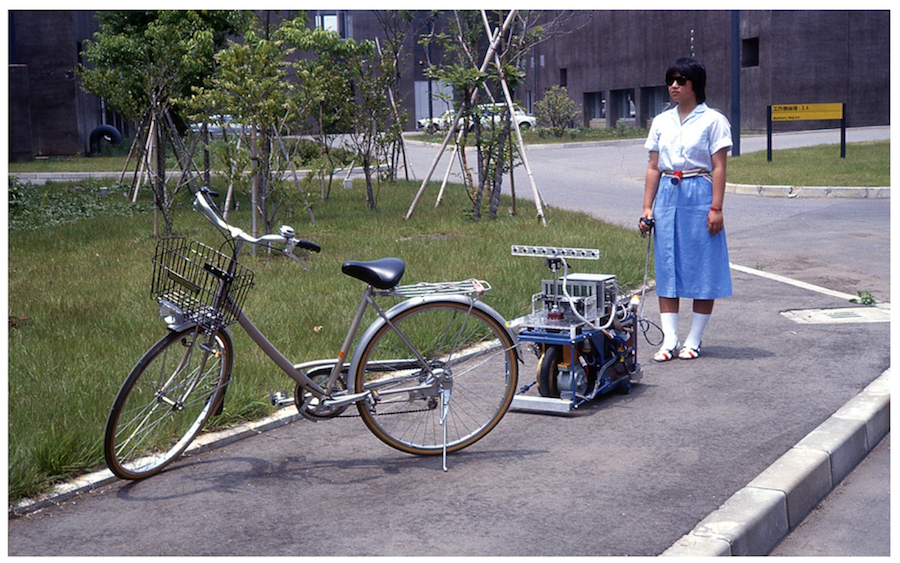
Photo. 4 MELDOG MARK III in the experiment to demonstrate an obstacle detection.
| SUMMARY | DETAILS | INTRODUCTION | GUIDE DOG ROBOT | NAVIGATION | COMMUNICATION |
| CONCLUSIONS | Research Episodes and Circumstances | REFERENCES |
COMMUNICATION
In order to guide a blind individual in accordance with the information acquired, an information communication channel between the master and the robot must be established.
When a robot which directs or guides a blind individual has somehow acquired information about the direction of, and width of, an unobstructed path along which it should lead the blind individual, the problem is the choice of sensory path display and its safe margins appropriate for presentation to the remaining exterior receptive senses of the blind individual. Quantitative comparison method of display scheme has been proposed and an optimal auditory display scheme has been sought [Tachi, et al., 1983].
In the MELDOG system the location of the master is measured by the robot in real-time by the triangulation of the ultrasonic oscillator put on the belt of the master and the two receivers on board the robot (See Fig.12). The result of the measurement is used to control the robot's speed to coincide with that of the blind master.
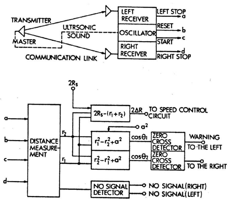
Fig. 12 Block diagram of measurement system of the master location using ultrasounds.
A safety zone is set behind the robot in which the master is supposed to walk (See Fig.13). The triangulation is also used to transmit warning signals from the robot to the master. When he is outside the zone he is warned by the robot, while he receives no feedback when he is safe. When the orientation of the master within the safety zone is not appropriate, the Master Guide detects the condition and informs the master. These signals are transmitted through a wired link and presented to the master in the form of electrocutaneous stimulation. One set of Ag-AgCl wet electrodes is placed on the skin of each brachium. The signals used are pulse trains with a pulse width of about 100 µs, the energy of which is controlled by a constant energy circuit [Tachi, et al., 1982 b].
In the test hardware MELDOG MARK I (See Photo.5) the repetition rate of the pulse train was set at 100 pps for normal warning stimuli that the master was outside the safety zone and 10 pps for warning that the master's orientation was inappropriate. For example, the signal presented to the right arm with 100 pps means the master should step to the right to come back to the safety zone and with 10 pps means (s)he should turn his/her body counterclockwise to correct his/her orientation [Tachi, et al., 1978 and 1981a].
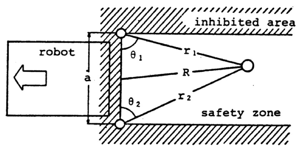
Fig. 13 Safety zone set behind the robot.
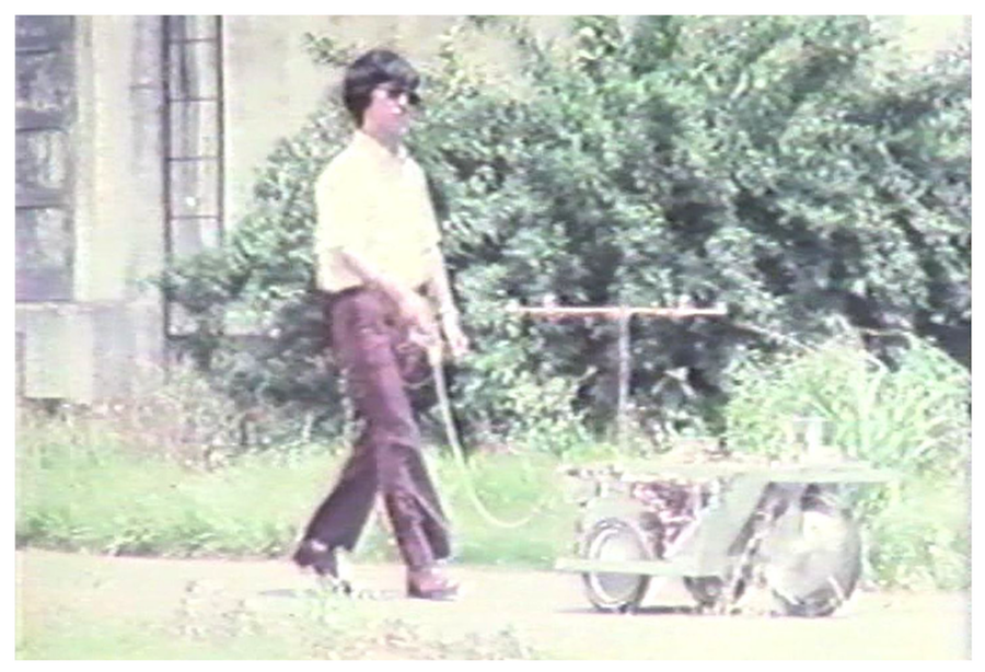
Photo. 5 Communication experiment with MELDOG MARK I.
| SUMMARY | DETAILS | INTRODUCTION | GUIDE DOG ROBOT | NAVIGATION | COMMUNICATION |
| CONCLUSIONS | Research Episodes and Circumstances | REFERENCES |
CONCLUSIONS
The idea of guiding a blind person using an autonomous robot and a method for the realization of the idea were proposed (Photo.6). The robot processes both the information stored in the memory of the robot and environmental information acquired by the sensors on board the robot and passes the processed information to the blind master.
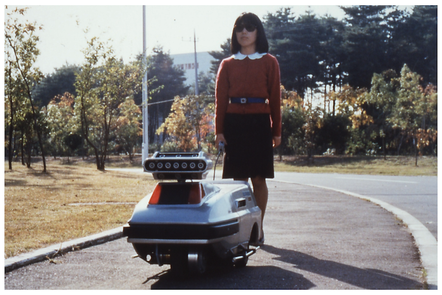
Photo. 6 General view of the guidance by MELDOG (MARK IV).
A navigation map is given to the robot prior to guidance. The robot travels according to the information on the navigation map. The error between the internal representaion of the environment (navigation map) and the real world is compensated by detecting landmarks in the real environment and correcting the robot's position and orientation according to the landmark location measurement. The landmark location data is already stored on the navigation map.
The feasibility of the navigation method was demonstrated both by computer simulation and outdoor experiments using the test hardware called MELDOG MARK II and MARK IV.
Some of the obstacle detection and avoidance functions were considered theoretically and the feasibility of the method was demonstrated by the test hardware called MELDOG MARK III and MARK IV.
Experiments concerning the transmission of course information and obstacle information via electrocutaneous stimulation were conducted using the test hardware called MELDOG MARK I and MARK IV.
The remaining problems include:
(1) The selection of general criteria for environmental objects as navigation landmarks, the detection method of the landmarks, and organization and utilization method of the navigation map with the information of the selected landmarks.
(2) Finding a more general obstacle detection and avoidance method.
(3) Finding an optimal choice of sensory display method of the navigation information acquired by the robot appropriate for presentation to the remaining exterior receptive senses of the blind individual.
| SUMMARY | DETAILS | INTRODUCTION | GUIDE DOG ROBOT | NAVIGATION | COMMUNICATION |
| CONCLUSIONS | Research Episodes and Circumstances | REFERENCES |
Research Episodes and Circumstances
–Excerpts from the book “Nature and Robots 6: Guide Dog Robot” published by Kiritani Publishing (1985) (in Japanese) – (Please note that the style here is narrative as the content is excerpted from a book intended primarily for juveniles.)
Let me tell you why I got involved in research on guide dog robots and how it all started.
Since my childhood I was very interested in the laws of nature and the mystery of the universe that are explained using principles of mathematics and physics. Besides, the mechanism of the body and workings of the mind of humans who came up with such thoughts were such a wonderful mystery for me. I thought it would be wonderful if I were able to study both of them, which were considered to be virtually impossible at that time.
On the other hand, I loved dogs, and had several pet dogs since my childhood days. Even after entering university where I studied machines, I sometimes had vague thoughts about whether it will be possible for human beings to communicate with machines, just as humans are able to communicate with dogs.
One night, in my second year in the university, when I was having such thoughts, I happened to switch on the radio and heard the recitation of a book titled, “Cybernetics.” “Cybernetics” refers to a field of study, where the workings of natural world, including human beings and society, are explained using principles of machines. i.e., mathematics and physics, and conversely, hints about principles of operating mechanical systems are obtained from human and animal movements and behaviors.
As the recitation ended, I felt as if I was struck by lightning. I finally came to know about research that involved linking humans and animals with principles of mathematics and physics. I jotted down the name of the author of the book, a man named Dr. Norbert Wiener from the USA, and I immediately went to the university library and searched for the book. Although it was not a book that was easy to read, I was completely absorbed in reading it.
Thereafter, I chose the department where I can study Cybernetics, entered graduate school, and became an Assistant Professor in the University of Tokyo. During that period, I always thought about humans and animals as I thought about mechanical systems. And among such thoughts, my interest in human beings with advanced capabilities that current computer technology cannot imitate, never ceased.
The mechanism department in the Mechanical Engineering Laboratory (MEL) where I started working at from spring, 1975, was a perfectly suitable place for such research. MEL, at that time, was transitioning from research purely on mechanical systems to research on mechanical systems that can realize movements similar to human beings. At that time, with the aim of making such technology useful in social welfare, research on a prosthetic arm that utilize the electric potential generated in human muscle (myoelectric signals), had already begun. I also took part in such research, but I was interested in not just such mechanisms, but more in research about how to realize robots that have intelligence. To realize human capability in machines is what research in robots is all about. However, robots with such functions usually were limited only to a particular human capability and implementing that function using machines, and there was no robot that had realized intelligent human capability in its entirety at that time.
In view of this, I started to think whether it was possible to realize in machines the intelligence of animals, which is slightly lower than human beings. At the same time, I always thought that such capability must be useful to human beings.
One night, while I was having such thoughts, I took my pet dog out for a walk. As we entered the woods, it was pitch dark as it was a night without any moonlight. However, the dog walked along with ease. It was then that the question of, “How about a guide dog?” suddenly crossed my mind.
I had read about guide dogs in ”The Book of Knowledge” primarily intended for children in the USA and was also long familiar with the name “Seeing-eye”. Also, I had read the book “Man Meets Dog” written by Austrian zoologist Konrad Lorenz, and knew about intelligence of dogs. I thought of realizing in robots the superior ability of guide dogs as the most useful function for human beings.
And it did not take long for me to come up with a concrete research plan for a guide dog robot based on the steadfast thoughts I had back then on intelligent robots that would be useful to human beings. At that time, I already had conceived the basic schematic design plan about what functions were needed and how to realize them.
I wrote down my thoughts in the form of a clearly defined plan, and consulted with Mr. Minoru Abe who was the head of the mechanism department at that time. Mr. Abe immediately agreed with my plan. Later I came to know that, like me, Mr. Abe was also fond of dogs.
I named the guide dog robot that I was planning to build, “MELDOG.” It was in September, 1975.
In research, there are two aspects, conceiving the idea and implementing it in a real system. A good idea is important, but it is more important to actually implement it in a real system. And on top of that, a large amount of time and effort from numerous individuals are needed for the implementation of the idea.
For the research about Guide Dog Robot, the period from September 1975 through spring of 1977 was used for preliminary research to concretely define the idea. I sought advice from various individuals as I visited guide dog training centers and facilities for blind or severely visually impaired people. Along with that, I also explored technologies from various fields of study such as measurement, information processing, control, communication, electronics, and mechanisms.
As a result, I was able to extract the principal functions of a guide dog and to design the technological system to fulfill the functions. They were obedience (in navigating or guiding a blind master), intelligent disobedience (in detecting/avoiding obstacles in his/her path), and (well-organized) man-machine communication (which does not interfere with his/her remaining senses). The basic idea of how to realize such functions in a way suitable for implementing in machines, was conceived at that time.
The next thing necessary in research is funding. However, such financial assistance cannot be obtained by just simply asking something like, “Please give us the funds.” Although I submitted the written proposal for special research in the spring of 1976, it was not until the spring of 1977 that formal approval was obtained, when the research could actually be started.
However, the research needs to go on even during such times. Thus, I actually started part of the research from 1976 without enough funding. Many individuals from MEL joined the research group, including Mr. Kazuo Tanie, Mr. Takefusa Ohno, Mr. Kiyoshi Komoriya, and Dr. Makoto Kaneko. Also, many undergraduate and graduate students such as Mr. Yuji Hosoda also joined after learning about guide dog robot research from one of my seniors, Dr. Sadao Fujimura. A wide circle of people interested in research was thus formed, and the guide dog research project was born.
Full-scale special research was formally started in 1977 to actually implement the idea in a real system. As the schedules became tighter, we were not just working late until ten or eleven in the night, many days we even worked overnight.
Thanks to such efforts, MELDOG MARK I, the first such system was completed quite early by the summer of that year. Thereafter, in quick succession, MARK II was completed in the winter of 1978, and MARK IIb was completed in the spring of 1979. The basic functions of MELDOG were confirmed using these prototypes.
To be honest, many other incidents did happen during this period. In one such incident, one early morning, after days of continuous work was about to be finished after successive overnight efforts, an inadvertent error completely damaged the electrical system. The work that had been painstakingly accomplished over a few months became useless in an instant. We were overwhelmed by the fatigue that had accumulated over the days. We were totally at a loss with what to do next. At that point, someone said, “let us call it a day and go home.”
However, the next day when we all met again, everyone looked as enthusiastic as before. The plan to reimplement the damaged part had already been thought out. Even with several such setbacks, as a group, our enthusiasm about MELDOG grew only stronger.
Thereafter, many other researchers and technicians joined the group, further invigorating the research. The MARK III prototype was completed in 1981, and in 1983, the last year of the first phase of the research plan, the latest version, MELDOG MARK IV, was completed. In that year, there were also some positive events.
One was that, then the Crown Prince and Princess, and their son Hironomiya (now the Emperor Emeritus and the Empress Emerita, and the Emperor) came to visit the research laboratory, and many other dignitaries including previous prime ministers and famous researchers also visited the laboratory. Among them, I was impressed by the talk of high expectation about the MELDOG project given by Mr. McPherson, who was the vice-chairman of The Guide Dogs for the Blind Association in UK.

Also, in September, 1983 our paper on communication between humans and MELDOG won the IEEE outstanding paper award in Biomedical Engineering. IEEE is one of the most authoritative academic societies in the world, and for the first time Japanese researchers had won an award in this field.
The research on a Guide Dog Robot that was conceived and brought to fruition in Japan, was finally internationally acclaimed. When we received the award, I reminisced about the memories of the research spanning eight years.
| SUMMARY | DETAILS | INTRODUCTION | GUIDE DOG ROBOT | NAVIGATION | COMMUNICATION |
| CONCLUSIONS | Research Episodes and Circumstances | REFERENCES |
REFERENCES
[Dodds, A.G., Armstrong J .D. and Shingledecker, C.A. 1982.] The Nottingham Obstacle Detector: Development and evaluation, J. Visual Impairment & Blindness, 75, pp. 203-209.
[Farmer, L.W., Benjamin, J.M. Jr., Cooper, D.C., Ekstrom, W.R., and Whitehead, J.J. 1975.]A teaching guide for the C-5 laser cane: An electronic mobility aid for the blind, Kalamazoo: College of Eciucation, Western Michigan University.
Kaneko, M., Tachi, s., and Komoriya, K. 1983.] A constructing method of data base for mobile robot navigation, J. of Mechanical Engineering Laboratory, 37, pp. 160-170.
[Kay, L. 1973.] Sonic glasses for the blind - Presentation of evaluation data, Research Bulletin of the American Foundation for the Blind, 26.
[Komoriya, K., Tachi, S., Tanie, K., Ohno, T., and Abe, H. 1983.]A method for guiding a mobile robot using discretely placed landmarks, J. Mechanical Engineering Laboratory, 37, pp. 1-10.
[Komoriya, K., Tachi, S., and Tanie, K. 1984.] A method for autonomous locomotion of mobile robots, J. Robotics Society of Japan, 2, pp. 223-232.
[Komoriya, K. et al. 1986] Kiyoshi Komoriya, Susumu Tachi and Kazuo Tanie: A Method of Autonomous Locomotion for Mobile Robots, Advanced Robotics, Vol.1, No.1, pp.3-19 (1986)
[Hann, R.W. 1974.] Technology and human rehabilitation: Prostheses for sensory rehabilitation end/or sensory substitution, Advances in Biomedical Engineering, 4, pp. 209-353.
[Morrissette, D.L., Goodrich, G.L. end Hennessey, J.J. 1981. ] A follow-up study of the Mowat Sensor's applications, frequency of use, and maintenance reliability, J. Visual Impairment & Blindness, 75, pp. 244-247.
[Russell, L. 1971.] Evaluation of mobility aids for the blind, Pathsounder travel aid evaluation, National Acad. Eng., Washington, D.C.
[Tachi, S. et al. 1978a.] Susumu Tachi, Kazuo Tanie, Kiyoshi Komiyama, Yuji Hosoda and Minoru Abe: "Study on Guide Dog (Seeing-Eye) Robot (I)", Bulletin of Mechanical Engineering Laboratory, No.32, pp.1-14 (1978)[PDF]
[Tachi, S., Komoriya, K, Tanie, K., Ohno, T., Abe, M., Hosoda, Y., Fujimura, S., Nakajima, H., end Kato, I. 1978b.] A control method of a mobile robot that keeps a constant distance from a walking individual, Biomechanisms, 4, pp. 208-219.
[Tachi, S., Komoriya, K., Tanie, K., Ohno, T., Abe, M., Shimizu, T., Matsuda, K. 1980.] Guidance of a mobile robot using a map and landmarks, Biomechanisms, 5, pp. 208-219.
[Tachi, S. et al. 1981 a.] Susumu Tachi, Kazuo Tanie, Kiyoshi Komoriya, Yuji Hosoda and Minoru Abe: Guide Dog Robot 〜Its basic plan and some experiments with MELDOG MARK I, Mechanism and Machine Theory, Vol.16, No.1, pp.21-29 (1981)[PDF]
[Tachi, S., Komoriya, K., Tanie, K., Ohno, T., and Abe, H. 1981b.] Guide Dog Robot - Feasibility experiments with MELDOG HARK III, Proceeding of the 11th International Symposium on Industrial Robots, Tokyo, Japan, pp. 95-102.
[Tachi, S., Komoriya, K., Tanie, K., Ohno, Abe, H., Hosoda, Y. 1982 a.] Course control of an autonomous travel robot with a direction-controlled visual sen or, Biomechanisms, 6, pp. 242-251.
[Tachi, S., Tanie, K., Komoriya, K., and Abe, M. 1982 b.] Electrocutaneous communication in Seeing-eye Robot (MELDOG), Proceedings of IEEE/EMBS Frontiers of Engineering in Health Care, pp. 356-361.
[Tachi, S., Mann, R.W., and Rowell, D. 1983.] Quantitative Comparison of Alternative Sensory Displays for Mobility Aids for the Blind, IEEE Transactions on Biomedical Engineering, Vol.BME-30, No.9, pp.571-577 (1983.9) [PDF]
[Tachi, S. and Komoriya, K. 1984.] Guide Dog Robot, in M.Brady et al.ed., The Robotics Research 2 (The Second International Symposium 1984), MIT Press, pp.333-349 (1985) [PDF]
[Tachi, S., Tanie. K., Komoriya, K., and Abe. M. 1985.] , Electrocutaneous Communication in a Guide Dog Robot (MELDOG), IEEE Transactions on Biomedical Engineering, Vol.BME-32, No.7, pp.461-469 (1985.7) [PDF]