| Details | References |
TELESAR (TELExistence Surrogate Anthropomorphic Robot) is an advanced type of teleoperation system that enables an operator at the control to perform remote manipulation tasks dexterously with the feeling of existing in a surrogate robot working in a remote environment.
An experimental telexistence system was realized which enables a human operator to experience the sense of being present in a remote real environment where a surrogate robot is located. A telexistence master-slave system for remote manipulation experiments was designed and developed, and an evaluation experiment of the telexistence master-slave system was conducted. By comparing the telexistence master-slave system with conventional master-slave systems, the efficacy of the telexistence master-slave system was verified, and the superiority of the telexistence method was demonstrated through tracking experiments.
The comparison results revealed the clear superiority of binocular vision combined with the natural arrangement of the head and the arm, which is the most important characteristic feature of telexistence.
Details
TELESAR (Telexistence Surrogate Anthropomorphic Robot)
Figure 1 shows a schematic diagram of the telexistence master-slave manipulation system, which consists of a master system with a head-coupled three-dimensional visual and auditory display, a master manipulator, a computer control system, and an anthropomorphic slave robot mechanism with an arm having seven degrees of freedom, a gripper hand, and a locomotive mechanism.
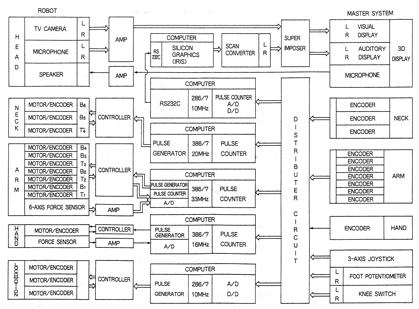
Fig. 1 Block diagram of the telexistence master-slave manipulation system.
A human operator wearing a 3D audiovisual display, which is designed to ensure the same distance and size cues as in direct observation from the location of the robot, is shown in Fig. 2. The audiovisual display is carried by a link mechanism with six degrees of freedom. The link mechanism cancels all gravitational force through a counter-balancing mechanism, which allows the operator's unconstrained movement in a relatively wide operation space (up/down: -500 ~400 mm; right/left: -300~300 mm; forward/backward: -300~800 mm).
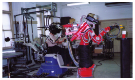
Fig. 2 General view of the telexistence master-slave manipulation system.
This setup also enables the display to follow the operator's head movements with sufficient precision to permit ordinary head movement. Regarding rotational movements, the mechanism is designed in such a way that the three rotational axes meet at one point. A parallel link mechanism is also used for attaining the roll motion as well as for load bearing. The degrees of freedom are arranged in such a way that the most important yaw motion (pan) is available at any orientation. The maximum inertial force applied to the head of the operator remains less than 5kgf (Fig. 3).
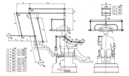
Fig. 3 Telexistence master system.
The master arm has ten degrees of freedom. Seven degrees of freedom are allocated for the arm itself, and three additional degrees are used to comply with the body movements. The movements of the operator's head, right arm, right hand, as well as other auxiliary movements (including the joystick operation and the feet movements) are measured by the master motion measurement system in real time without constraint. The measured signals corresponding to movements of the head, the arm, the hand, and any auxiliary movements are sent to computers. There are four computers (equipped with Intel 2861386 processors) which generate the command position of the slave head movement, the arm movement, the hand movement, and the locomotion of the slave robot, respectively.
All programs were written in the C language and run under MS-DOS, and the program sizes are 11572, 76983, 22611, and 86375 bytes, respectively. Calculations on each computer are synchronized by the movements of the human operator through the master system so that all computers are automatically coordinated.
The servo controller controls the movements of the slave anthropomorphic robot. The slave robot has a locomotive mechanism and a hand mechanism. The robot also has three degrees of freedom in the neck mechanism, on which a stereo camera is mounted. It has an arm with seven degrees of freedom, and a torso mechanism with one degree of freedom (waist twist). The dimensions and the arrangement of the degrees of freedom of the robot are designed to mimic those of the human body.
The range of each degree of freedom is set so that it can cover the movements of a human, while the speed is set to match the average speed of human movements (3m/sec at the wrist). The weight of the robot is 60kg, and the arm can carry a 1kg load at a maximum speed of 3m/sec. The precision of position control of the wrist is 1mm. A six-axis force sensor installed at the wrist joint of the slave robot measures the force and the torque exerted upon contact with an object, which is used to adjust the mechanical impedance of the robot's arm to a compliant predetermined value.
The robot moves by a planar motion mechanism whose position is assigned in a polar coordinate system (r,), where r = 500~1500 mm and = 0~270 deg. The orientation of the robot is assigned by the waist rotation angle of the robot, where = -150~150 deg. A hand mechanism with one degree of freedom, which can either pinch or grasp, was also designed. It is capable of pinching small objects (with a diameter of 2 mm) as well as rather large objects (with a diameter of up to 114 mm).
The hand uses a parallel link mechanism and a ball screw. Grasping of cylindrical objects with a minimum diameter of 15 mm can be performed by making contact at three points, which makes the grasping stable. Strain gauges, which measure the grasping force, are placed on two finger links. The average grasping force is 5kgf. Furthermore, measurements of the opening are performed by using an encoder attached to a DC motor. Position control with an average resolution of 0.01mm is attained, and a six-axis force sensor is installed at the wrist position. The hand is made of durable aluminum and weighs 620g, including the force sensor.
The vision system of the slave robot consists of two color CCD video heads from TV cameras. Each CCD has a resolution of 420,000 pixels and its own optical system with a focal length of f = 12mm (field of view 40 deg) and an aperture of F1.6. Focus is automatically controlled with the TTL AF method. The distance between the two cameras is set to 65mm, and the two cameras are aligned parallel to each other.
Regarding the auditory system, two microphones are placed 243mm apart from each other, and the same positional relation is used for the auditory display of the master system. A small speaker is placed at the location of the mouth, which transmits the operator's voice. Figure 4 shows a general view of the telexistence surrogate anthropomorphic robot TELESAR under operation of building blocks.
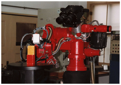
Fig. 4 TELESAR under operation of building blocks.
The stereo visual and auditory input system mounted on the neck mechanism of the slave robot gathers visual and auditory information from the remote environment. This information is sent back to the master system and is applied to the specially designed stereo display system in order to evoke the sense of presence at the remote location in the operator. The measured information on the human movement is used to change the viewing angle, the distance to the object, and the conditions of the object and the hand in real time. The operator observes the 3D remote environment in front of his or her eyes, which changes according to their movements.
The stereo visual display is designed in accordance with a developed procedure which assures that the 3D view maintains the same spatial relations as in the case of direct observation. A pair of 6-inch LCDs (H720 X V240 pixels) are used together with a convex lens system. The compact arrangement of a display system suitable for use as the master manipulation system was made possible by arranging the two mirrors so that the LCDs can be placed on the upper side in front of the operator (Fig. 5).
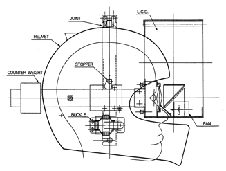
Fig. 5 Telexistence head-mounted display.
Manipulation Experiments
Experiments which quantitatively evaluate the typical characteristics of the telexistence master-slave system were conducted. The most noticeable differences between telexistence and/or virtual reality and the conventional human-machine interface is that a virtual environment providing a sense of presence has the following features:
(1) The virtual environment is a 3D space which feels natural to the user (3D Life-sized Space),
(2) it allows the user to act freely and allows the interaction to take place with natural movements in real time (Real-time Interaction), and
(3) it allows the projection of the operator in the form of a virtual humanoid or a surrogate robot (Self Projection).
Thus, the most important features of telexistence include natural 3D vision (closely approximating direct observation), which follows the operator's head movements in real time, and a natural correspondence between visual information and kinesthetic information, where the operator observes the slave's anthropomorphic arm at the position where his or her arm should appear. This is regarded as the basis of the feeling of existence, which allows the operator at the control to perform tasks which require real-time coordination of hand and eye, as in the case of direct object manipulation.
In order to obtain experimental proof and a quantitative evaluation of the effects of the three features of telexistence, the following experiment was conducted. The following five visual display methods were compared:
1. Direct observation;
2. HMD (B): Binocular Head-Mounted Display and a stereo camera mounted on the slave robot, whose orientation, i.e., pitch, roll, and yaw, are controlled to follow the movements of the operator;
3. HMD (M): Monocular Head-Mounted Display and one camera mounted on the slave robot, whose orientation, i.e., pitch, roll, and yaw, are controlled to follow the movements of the operator;
4. CRT (H): A conventional CRT display placed in front of the operator with a field of vision of 45 deg and a camera placed at the eye position of the robot head, whose orientation is fixed to the direction of the movement of the target;
5. CRT (0): Conventional CRT display placed in front of the operator with a field of vision of 45 deg and a camera placed 30 deg to the side of the robot, whose orientation is fixed to the direction of the movement of the target.
The head-mounted display was designed in accordance with the procedure that has been previously described [1, 2, 3, 17]. In the HMD (M) mode, only the right-side display of the binocular system was used. The field of view was 40 deg for each eye.
Figure 6 shows the experimental arrangement of the slave robot and the linear positioner. A target was fixed to the moving part of the linear positioner, which was driven by random noise with a maximum stroke of +100mm along the depth axis of the operator's observation direction.
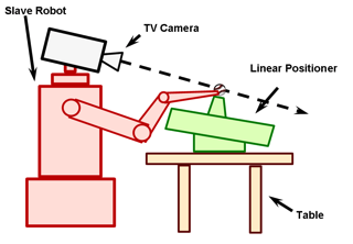
Fig. 6 Experimental arrangement.
The operator was asked to place the tip of the slave robot's manipulator at the position of the target by using the master manipulator under several display conditions (conditions 2 through 5). Since the target moved randomly, the operator was forced to follow the target (tracking). In this experiment, the target's moving direction was elaborately arranged so that it coincides with the direction of observation in order to eliminate mutually dependent effects and to single out the effects of the head movements of the operator, the binocular observation, and the matching of kinesthetic and visual information.
Under condition 1 (direct observation), the operator was at the position of the slave robot instead of the robot and tracked the target with the master manipulator while observing the target directly. This condition was used as the control data.
Pseudorandom noise was used as the target position input, as follows:
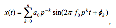
where p = 1.25, n =17, f0=0.0326 Hz, and  is a random number.
The experimental tracking system is shown in Figure 7. As shown in the figure, the pseudorandom noise x(t) was applied to the linear positioner containing the target, and the operator attempted to follow the random movements of the target by manipulating the master manipulator while observing the target and the slave manipulator through a head-mounted display or a conventional CRT display under several display conditions.
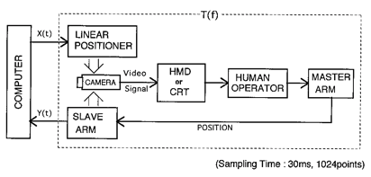
Fig. 7 Block diagram of the evaluation system.
The human operator's tracking trajectory y(t) along the linear positioner's coordinate was calculated by using the kinematics of the slave manipulator and the measured seven joint angles of the manipulator. The performance was evaluated by comparing the transfer function of the human operator T(f), which was estimated using x(t) and y(t) for each of the above mentioned display methods.
T(f) is estimated as follows:
![]()
where Φxy is the cross-spectrum between the input signal x(t) and the output signal y(t), and Φxx is the power spectrum of signal x(t). Signals x(t) and y(t) are measured for a finite amount of time in order to determine their Fourier transforms. The uppercase letters denote the Fourier transform of the corresponding signals denoted by lowercase letters. In addition, the asterisk denotes the complex conjugate, and E[ ] denotes the ensemble average.
The control cycle of the master-slave system and the linear positioner was 10msec. The output response was sampled every 30msec. FFTs (fast Fourier transforms) of 1024 points were employed, and the cross-spectrum was measured by using the frequency averaging technique for each of the display methods. This process was repeated five times in order to obtain an ensemble average of the cross-spectrum, after which the transfer function was estimated as the ratio of the average cross-spectrum and the power spectrum for each display method.
Figure 8 shows an example transfer function. The amplitude (gain) and the phase of the human transfer function under the tracking task are shown as a function of the frequency. The crossover model can be applied as a first-order approximation. According to the crossover model of McRuer [D.T. McRuer and H.R. Jex: A review of quasi-linear pilot models, IEEE Transactions on Human Factors Engineering, Vol.HFE-8, pp.241-249, 1967.], the transfer function in the region of the crossover frequency can be described as follows:
![]()
where ωc is the crossover frequency corresponding to the gain compensation of the operator performing tracking by using the display, and is the effective time delay due to both reaction time and neuromuscular dynamics.
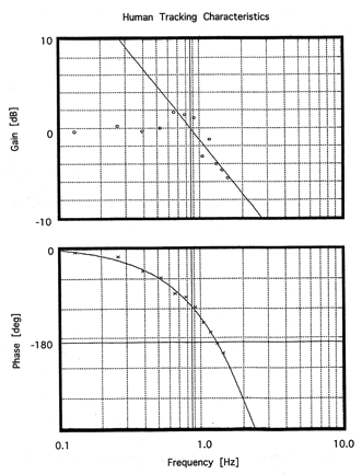
Fig. 8 An example of the human tracking characteristics.
The overall performance of the model is improved by increasing the equivalent gain and reducing the equivalent time delay. The two parameters Ke and Te describe the overall characteristics of tracking based on using this display, just as in the case of the evaluation of the mobility aid for the blind [Tachi, Mann, and Rowell, 1983].
Thus, the quantity
![]()
was selected for the purpose of determining and evaluating quantitatively the effectiveness of each display method, where (i) is the display method number described above.
In order to estimate the effective gain and the effective time delay, a line with a slope of -20dB/decade was fitted to the amplitude of the transfer function near the crossover frequency, and by using the least squares method, the crossover frequency fc was measured for each of the five display schemes.
The phase margin  was measured as = 180 - Pc , where Pc is the phase value at the crossover frequency. The effective gain and the effective time delay Te were calculated from the following formulae:
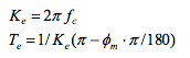
Figure 9 shows the results for an operator using each of the five display schemes. These two parameters fc and Te are plotted in Fig. 4.26, which clearly shows the superiority of HMDs over conventional CRTs. When HMDs are used, an operator can control the directions (pitch, roll, and yaw) of the slave camera in accordance with the movements of his or her head, while the size and the perspective view of the slave manipulator and the target are the only cues in the case of CRTs. This is the main reason for the observed differences.
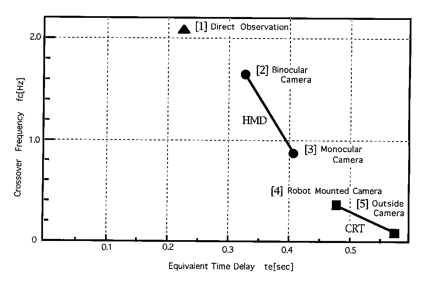
Fig. 9 Comparison results.
In the HMD group, the binocular display is associated with higher performance than the monocular display. Since no translational movement of the slave camera is allowed in this experiment, the superiority of binocular display is expected. Although we did not conduct a quantitative evaluation for the monocular display, which allows the translational motion of the slave camera following the movements of the human operator's head, our preliminary experiments suggested that the performance of monocular HMD with respect to translational movement improved with the use of motion parallax. The effects of motion parallax need further quantitative evaluation.
The differences between the CRT groups are due to the arrangement of the cameras and the slave manipulator. If we limit the arrangement to only the type described in condition 5, i.e., if the line of sight of the camera coincides with the direction of linear movement of the target, this result clearly indicates the effectiveness of the natural arrangement of the cameras and the manipulator close to the positional relations of the human eyes and the arm used for manipulation.
The experiment was conducted with five operators (all males in their thirties), and they showed the same tendency, although their absolute evaluation values were different. Figure 10 shows the normalized averaged evaluation value of each display scheme. The performance under direct observation was used as a standard, and its value was set to 1.
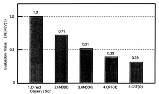
Fig. 10 Comparison result using the EV criterion.
Figure 11 shows the comparison results, in which the root mean square error of the output from the input was used as a criterion for comparison. The comparison results showed the same tendency as that shown when the EV criterion was used.
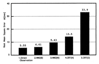
Fig. 11 Comparison results based on using the root mean square value.
The HMD (B) display type results were superior to all other conditions except direct observation. In this regard, the method of observation was not the only difference between the direct observation and the HMD (B) observation. The use of a master manipulator as the tracking manipulator means that the direct observation is free from the disadvantageous effects of the dynamics of the slave manipulator. Future experiments are necessary in order to eliminate these differences.
(Revised from Susumu Tachi and Ken-ichi Yasuda: Evaluation Experiments of a Telexistence Manipulation System, Presence, Vol.3, No.1, pp.35-44, 1994.[PDF] )
References
1) S. Tachi, K. Tanie, K. Komoriya and M. Kaneko: Tele-existence (I) :Design and Evaluation of a Visual Display with Sensation of Presence, Proceedings of RoManSy'84 The Fifth CISM-IFToMM Symposium, pp. 245-254, Udine, Italy (1984.6) [PDF]
2) S. Tachi and H. Arai: Study on Tele-existence(II)-Three Dimensional Color Display with Sensation of Presence-, Proceedings of the '85 ICAR(International Conference on Advanced Robotics), pp. 345-352, Tokyo, Japan (1985.9) [PDF]
3) S. Tachi, H. Arai, I. Morimoto and G. Seet: Feasibility Experiments on a Mobile Tele-existence System, Proceedings of The International Symposium and Exposition on Robots, pp. 625-636, Sydney, Australia (1988.11) [PDF]
4) S. Tachi, H. Arai and T. Maeda: Robotic Tele-existence, Proceedings of the NASA Conference on Space Telerobotics, pp. 171-180, Pasadena, California, USA (1989.1)[PDF]
5) S. Tachi, H. Arai and T. Maeda: Development of an Anthropomorphic Tele-existence Slave Robot, Proceedings of the International Conference on Advanced Mechatronics, pp.385-390, Tokyo, Japan (1989.5) [PDF]
6) S. Tachi, H. Arai and T. Maeda: Tele-existence Visual Display for Remote Manipulation with a Realitime Sensation of Presence, Proceedings of the 20th International Symposium on Industrial Robots, pp.427-434, Tokyo, Japan (1989.10) [PDF]
7) S. Tachi: Tele-existence and / or Cybernetic Interface Studies in Japan, Human Machine Interface for Teleoperators and Virtual Environments, NASA Conference Publication, pp. 34-35, Santa Barbara, California, U.S.A (1990.3) [PDF]
8) S. Tachi, H. Arai and T. Maeda: Tele-existence master Slave System for Remote Manipulation, Proceedings of the IEEE International Workshop on Intelligent Robotics and Systems '90 (IROS '90), pp.343-348, Tsuchiura, Japan (1990.7)[PDF]
9) S. Tachi, H. Arai and T. Maeda: Tele-existence Master Slave System for Remote Manipulation (II), Proceedings of the 29th IEEE Conference on Decision and Control, Vol.1, pp.85-90, Honolulu, Hawaii, USA (1990.12)[PDF]
10) S. Tachi, H. Arai, T. Maeda, E. Oyama, T. Tsunemoto and Y. Inoue: Tele-existence Experimental System for Remote Operation with a Sensation of Presence, Proceedings of '91 International Symposium on Advanced Robot Technology ('91 ISART), pp.451-458, Tokyo, Japan (1991.3)[PDF]
11) S. Tachi, H. Arai and T. Maeda: Tele-existence Master Slave System for Remote Manipulation, Video Proceedings of the International Conference on Robotics and Automation, G1, Sacrament, California, USA (1991.4) >>YouTube
12) S. Tachi, H. Arai, T. Maeda, E. Oyama, N. Tsunemoto and Y. Inoue: Tele-existence in Real World and Virtual World , Proceedings of the fifth International Conference on Advanced Robotics ('91 ICAR), pp.193-198, Pisa, Italy (1991.6) (Invited Paper) [PDF]
13) S. Tachi: Sensor and Sensing Systems in Advanced Robotics , Digest of Technical Papers of the 1991 International Conference on Solid-State (Transducers '91), pp.601-606, San Francisco, California, USA (1991.6) (Invited Keynote Paper) [PDF]
14) S. Tachi: Tele-existence - Toward Virtual Existence in Real and/or Virtual Worlds -, Proceedings of the International Conference on Artificial Reality and Tele-existence (ICAT '91), pp.85-94, Tokyo, Japan (1991.7) [PDF]
15) S. Tachi, H. Arai and T. Maeda: Tele-existence: An Advanced Remote Operation System with a Sensation of Presence, SMiRT 11 Transactions, pp.325-330, Tokyo, Japan (1991.8)
16) S. Tachi, H. Arai and T. Maeda: Measurement and Control in Tele-existence and Artificial Reality, Proceedings of the 12nd Triennial World Congress of the International Measurement Confederation (ACTA IMEKO 1991), pp.1241-1248 (1991.9) (Invited Keynote Paper)[PDF]
17) T. Maeda and S. Tachi: Development of Light-weight Binocular Head-mounted Displays, Proceedings of the Second International Symposium on Measurement and Control in Robotics (ISMCR '92), pp.281-288, Tsukuba, Japan (1992.11) [PDF]
18) Susumu Tachi and Ken-ichi Yasuda: Evaluation Experiments of a Telexistence Manipulation System, Presence, Vol.3, No.1, pp.35-44 (1994.2) [PDF]