[ Summary | DETAILS | References ]
Summary
RePro3Dは,高輝度LCDとレンズからなる高密度プロジェクタアレイを用いた投影型の立体ディスプレイ手法です.上下・左右の運動視差を持ったCGが空中に結像した3D映像を裸眼で観察することができます.
また,赤外カメラによって手と3D映像の接触状態を認識し,指先に装着した触覚提示装置によってキャラクタに触ったときの触感を生成することができます.
DETAILS
RePro3D: RPT-Based Full-Parallax Autostereoscopic 3D
(Yoshida et al., 2010, 2011)
Autostereoscopic 3D means the creation of 3D images based on the human binocular perception of 3D depth without the use of special headgear or glasses by the viewer. Most common stereoscopic displays are based on the binocular stereo concept. However, binocular-stereo-based displays without motion parallax cannot render an accurate image and cannot create images that would provide different perspectives of the same image from multiple points of view. Motion parallax plays an important role in the manner in which humans perceive 3D shapes. Multiview autostereoscopic 3D provides the perception of left–right motion parallax, and full-parallax autostereoscopic 3D provides the perception of both left–right motion parallax and up-down motion parallax. Full-parallax 3D, which provides different perspectives according to the viewing direction, is not only useful for motion parallax for a single viewer but also necessary for simultaneously displaying stereoscopic images to a large number of people.
Most conventional multiview or full-parallax autostereoscopic3Dsystems are based either on the parallax barrier method or on the integral photography (IP) method. In the parallax barrier method, a barrier with a number of slits is placed in front of an image source so that a different pixel is seen from different viewing angles. However, the parallax barrier method is not capable of generating vertical parallax, such that full-parallax autostereoscopic 3D cannot be attained. Thus, IP is the most appropriate method of realizing full-parallax autostereoscopic 3D. In the IP method, a light field is reproduced by placing an array of microlenses in front of an image source. In the IP method, the number of viewpoints can easily be increased depending on the resolution of the image source. However, because the resolution of the 3D image from a viewpoint depends on the number of lenses per unit area, the lenses must be sufficiently small to have the necessary resolution. Thus, only relatively crude implementations have yet been produced by using today’s technology.
Moreover, for the user to view the displayed object as a real object, full-parallax autostereoscopic 3D is not sufficient. In addition to the displayed 3D image in full-parallax autostereoscopic 3D, it should be superimposed—not on a screen — but in real space. That is, a full-parallax autostereoscopic 3D image must be produced as an aerial image floating in the air. However, conventional IP produces 3D images in front of a screen and cannot produce aerial images.
Figure 1 shows the basic principle of RePro3D, which is the RPT based full-parallax autostereoscopic 3D display method. When images from a projector array are projected onto a retro-reflector, light is reflected only in the direction of each projection lens. Images from the projector array are projected onto the retro-reflector. When users look at the screen through a half-mirror, they can view, without the use of glasses, a 3D image that has motion parallax. RePro3D can generate vertical and horizontal motion parallax. An identical number of viewpoints are created on either side of the axis of symmetry of the half-mirror.
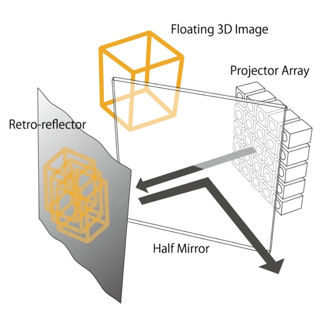
Fig. 1 Basic principle of RePro3D, consisting of a projector array, a half-mirror, and a retro-reflector.
The resolution of the image from each viewpoint depends on the projector resolution, and the number of viewpoints is equal to the number of projectors. Therefore, it is easy to improve the image resolution. It is also easy to produce a full-parallax autostereoscopic 3D image as an aerial image, i.e., floating in the air, because it inherently uses a half-mirror as its component.
When a large number of projectors are arranged in a matrix, a 3D image can be viewed from multiple viewpoints. To realize smooth motion parallax, the density of projectors in the projector array must be sufficiently high. However, with commercially available projectors, it is difficult to form a projector array in which the projectors are located very close to each other. One reason for this is that the distance between adjacent viewpoints is limited by the size of each projector. In addition, the system scale would increase, and because of the large number of video outputs, the system cost would also increase.
Therefore, a virtual high-density projector array has been developed by arranging a single LCD display, a lens array, and a Fresnel concave lens. The distance between viewpoints can be diminished by making a virtual lens array of the real lens array by using the Fresnel concave lens. Because an LCD display is used for the projector array, a single video output can be used as an image source, the cost of which is lower than that of using many image sources for plural projectors.
Figure 2 shows such an arrangement without a Fresnel concave lens. The system consists of a number of lenses, an LCD, a half-mirror, and a retroreflector, which acts as the screen. The lenses are located at an appropriate distance from the imaging area of the LCD so that the projected areas of the projection lenses overlap. Shield plates are placed between the lenses to prevent light from other viewpoints from entering a lens. Figure 8.25 shows the lateral view of the optical system; the overhead view would be identical to the lateral view. The luminance of the projected image depends on LCD luminance, viewing angle, and retro-reflector performance. The resolution of the image from each viewpoint depends on the LCD resolution. The number of viewpoints is equal to the number of projection lenses.
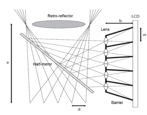
Fig. 2 RepRo3D configuration.
Figure 3 shows the prototype. We used 42 projection lenses, each of diameter 25mm and focal length 25 mm. The Fresnel concave lens used in the prototype was 370mm in diameter, and its focal length was −231 mm. We used a high-luminance LCD with a resolution of 1680×1050 pixels and a luminance of 1000 cd/m2, and a retro-reflector (Reflite, 8301). The projection lenses were arranged in a 6 (rows) ×7 (columns) matrix; therefore, the total number of viewpoints was 42. The resolution of the projected image seen from each viewpoint was 175 × 175 pixels. The distance between viewpoints was 16 mm. The device was able to project up to 400mm from the user’s viewpoint. The image was projected in a space of size 200 × 200 × 300 mm.
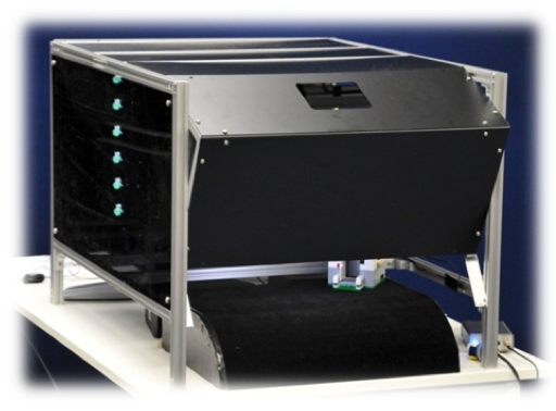
Fig. 3 General view of RepRo3D prototype.
Figure 4 shows the 3D object that was projected onto the retro-reflective screen and that was able to be seen from several viewpoints. The positional relationship of each displayed object changed according to the change of viewpoint. This finding indicates that our proposed method can produce a stereoscopic image superimposed in real space with smooth motion parallax.
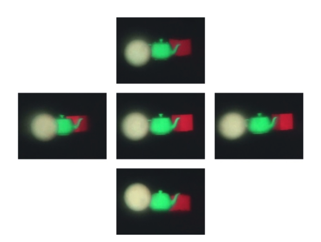
Fig. 4 Motion disparity.
We placed an infrared (IR) camera (Point Gray Research, Firefly MV) with an IR pass filter and IR LEDs above the projected area to capture the user’s hand movements, as shown in Fig. 5. Then, we implemented the user input system, which recognizes the degree of contact between the user’s hand and the displayed image. Using this function, we built an application that enables the user to touch a character floating in space. If the user touches the character, the character reacts to the user’s touch, and the user can perceive this reaction by looking at the changes in the character’s appearance and by sound cues.
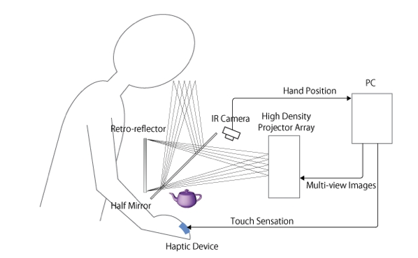
Fig. 5 Visuo-haptic system overview.
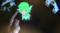
Figure 6 shows the application, in which the character, an animated fairy floating in real space, reacts when touched by the user’s finger. In addition, the user wears a haptic device on his/her finger. When the user touches the 3D image, he/she feels a tactile sensation generated by the haptic device.
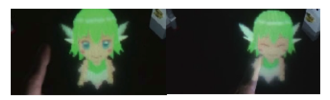
Fig. 6 Interaction with a virtual character.
The mechanism that produces the sensation on the user’s finger is based on Gravity Grabber technology (Minamiza et al., 2007). Gravity Grabber produces finger-pad deformation by using a pair of small motors and a belt. To create a “pushing” sensation, the dual motors are driven in opposite directions so that they roll up the belt, thus delivering vertical stress to the user’s finger pad (see Fig. 7).
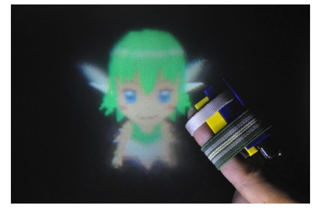
Fig. 7 Interaction with haptic feedback via Gravity Grabber.
The belt tension is determined by the degree of contact between the finger and the 3D image. The results of tests using the RePro3D prototype verify that our proposed method produces autostereoscopic images superimposed in real space, with smooth motion parallax. In this prototype, we also realized a user interface that enables users to interact physically with a virtual character floating in space. Based on the results, we demonstrated that RePro3D provides a visual and haptic interface that enables users to see and touch a virtual 3D object as if the object were real.
References
[Yoshida et al. 2010] Takumi Yoshida, Sho Kamuro, Kouta Minamizawa, Hideaki Nii and Susumu Tachi: RePro3D: Full-parallax 3D Display using Retro-reflective Projection Technology, ACM SIGGRAPH 2010, Emerging Technologies, Los Angeles, CA, USA (2010. 7) [PDF]
[Yoshida et al. 2011] Takumi Yoshida, Keitaro Shimizu, Tadatoshi Kurogi, Sho Kamuro, Kouta Minamizawa, Hideaki Nii and Susumu Tachi: RePro3D: Full-parallax 3D Display with Haptic Feedback using Retro-reflective Projection Technology, Proceedings of International Symposium on Virtual Reality Innovations (ISVRI 2011), Singapore, pp.49-54 (2011. 3) [PDF]
[Minamizawa et al. 2007] Kouta Minamizawa, Souichiro Fukamachi, Hiroyuki Kajimoto, Naoki Kawakami and Susumu Tachi: Wearable Haptic Display to present Virtual Mass Sensation, 34th Int. Conf. On Computer Graphics and Interactive Techniques (ACM SIGGRAPH 2007), Sketches, San Diego, USA (2007.8) [PDF]