TELESAR VI is an avatar robot system developed as an embodied telexistence platform in the Embodied Media Project. As a self-incarnation (avatar), it enables a person to perform various actions ranging from watching and listening to speaking, from a remote location, as if he/she were physically present.
Susumu Tachi, Yasuyuki Inoue and Fumihiro Kato: TELESAR VI: Telexistence Surrogate Anthropomorphic Robot VI, International Journal of Humanoid Robotics, Vol. 17, No. 5, p.2050019(1-33) (2020.10) [PDF]
Summary
TELESAR VI is a successor to TELESAR V, which played a major role in the selection of avatar as the next theme of XPRIZE. One feature of TELESAR VI is that it realizes 67 DOFs, an unparalleled feat in the world of telexistence robots. As an index evaluating the extent to which the body can freely move, DOF, which represents the number of joints that can be independently controlled, is used. TELESAR V had 53 DOFs; in TELESAR VI, on the other hand, we successfully increased it to as much as 67. In the past, there were 64- and 114-DOF humanoid robots. However, they did not permit telexistence. In TELESAR VI, telexistence was realized by controlling the 67 DOFs of an avatar robot concurrently with the unconstrained measurements of 134 DOFs of humans, together with the transmission of the realistic sense of vision and hearing. The 67 DOFs can be broken down as follows: three in the head, six in the torso, seven for each arm, six for each leg, and 16 for each hand. With the avatar robot having almost as many DOFs as human beings, human-like actions can be naturally conveyed to it. Further, having legs that can move at one's disposal largely increases the sense of possession of a body, enabling operators to experience their new robotic body more vividly. The avatar robot can operate in a sitting position since the main area of operation is intended to be manipulation and gestural.
The following is the web version of the paper on TELESRAR VI, Susumu Tachi, Yasuyuki Inoue and Fumihiro Kato: TELESAR VI: Telexistence Surrogate Anthropomorphic Robot VI, International Journal of Humanoid Robotics, Vol. 17, No. 5, p.2050019(1-33) (2020.10)
TELESAR VI: Telexistence Surrogate Anthropomorphic Robot VI
Susumu Tachi, Yasuyuki Inoue and Fumihiro Kato
ABSTRACT
Telexistence refers to the general technology that allows humans to experience the real-time sensation of being in another place, interacting with a remote environment, which may be real, virtual, or a combination of both. It also refers to an advanced type of teleoperation system that allows an operator behind the controls to perform remote tasks dexterously with the feeling of being in a surrogate robot working in a remote environment. Telexistence in a real environment through a virtual environment is also possible. The concept was originally proposed by the first author in 1980, and its feasibility has been demonstrated through the construction of alter-ego robot systems called Telexistence Surrogate Anthropomorphic Robot (TELESAR) I–V. TELESAR VI is a newly developed telexistence platform for the ACCEL Embodied Media Project. It was designed and implemented with a mechanically unconstrained full-body master cockpit and a 67 degree of freedom (DOF) anthropomorphic avatar robot. The avatar robot can operate in a sitting position since the main area of operation is intended to be manipulation and gestural. The system provides a full-body experience of our extended “body schema," which allows users to maintain an up-to-date representation in space of the positions of their different body parts, including their head, torso, arms, hands, and legs. All ten fingers of the avatar robot are equipped with force, vibration, and temperature sensors and can faithfully transmit these elements of haptic information. Thus, the combined use of the robot and audiovisual information actualizes the remote sense of existence, as if the users physically existed there, with the avatar robot serving as their new body. With this experience, users can perform tasks dexterously and feel the robot's body as their own, which provides the most simple and fundamental experience of a remote existence.
Keywords: Telexistence; telepresence; teleoperation; master-slave system; haptic primary colors; embodied media.
| 1. Introduction | 2. An Overview of TELESAR VI | 3. Mechanical Specifications of TELESAR VI |
| 4. Master-Slave Control System of TELESAR VI | 5. Principle of Haptic Primary Colors |
| 6. Haptic Telexistence for TELESAR VI | 7. Feasibility Experiments (Demonstration) | 8. Conclusion | References |
1. Introduction
Telexistence is a neologism coined by combining the prefix “tele" and the word “existence." It is a concept that denotes an extension of human existence, wherein a person exists wholly in a location, other than his or her actual current location, and can perform tasks freely there. The term also refers to the system of science and technology that enables realization of the concept.
The notion of telexistence [1] was conceptualized in September 1980 in Japan [2], and a patent was filed for it [3]. The first visual telexistence device was developed in Japan [4] where its experimental results were presented; subsequently, the findings were presented at an international conference.5 Experiments have been conducted using a mobile telexistence system [6], telexistence surrogate anthropomorphic robot (TELESAR) [7], an anthropo-morphic telexistence robot system, and a bipedal robot [8], and its feasibility and utility have been demonstrated.
The idea of mutual telexistence, which provides both the sense of presence and the sense of self-presence was presented in 1999 [9], and a mutual telexistence visual system based on the retro-reflective projection technology (RPT) was tested [10]. In the 2005 Aichi World Exposition, TELESAR II [11], an anthropomorphic mutual telexistence robot system was constructed, and the feasibility and utility of mutual telexistence were demonstrated through an open experiment.
With the goal of unraveling self-recognition and self-existence, TELESAR III, a telexistence master-slave system that can interact with humans with ease, was constructed, and assessment experiments that centered around the extension of body and self-recognition were performed [12].
In the subsequent TELESAR IV system, VORTEX, an omnidirectional stereo camera, was mounted on a surrogate omnidirectional mobile robot with an arm and a hand, and was used to conduct a test demonstration for people to remotely participate in an event. Using TWISTER [13], the remote participant can, with no special glasses, observe the 360°panoramic, full-color, real-time, stereo image sent from VORTEX, hear sounds from all directions, and communicate with local participants at the event hall with gestures and the sense of presence. Furthermore, the local participants at the event hall can have regular conversations and even watch from their preferred angle, the image of the remote participant, captured from the cameras set up such that they rotate outside TWISTER, as projected onto the robot through the RPT. The on-site local participant can even shake hands with the remote participant and have the sense of presence of the remote participant [14]. The above mentioned system demonstrated the feasibility and utility of telexistence with regard to the visual and auditory senses. To further convey the sense of touch (somatosensory perception), TELESAR V was built [15]. The sense of touch can be divided into proprioceptive and cutaneous sensations. The feasibility and utility of proprioception, another name for kinesthesia, had been demonstrated in teleoperation prior to telexistence through force-feedback bilateral control and impedance control.
In TELESAR V, we sought to implement haptic telexistence, which primarily conveys cutaneous sensations, as well as “the sense of smoothness," “the sense of roughness," and “the sense of warmth," together with proprioception, by actively exploring the environment. A remotely located slave robot tracks the movement of a person, and the visual field and sound captured by the eyes and ears of the robot mounted on the head of the slave are presented realistically to the person through the master's visuo-auditory presentation system. Moreover, the arms and hands of the slave track the movement of a person's arms and hands, and make contact with a target object. This allows the person to obtain haptic information that does not contradict the visual and auditory information of the object and to have the feeling of being present at the location of the robot despite being in a remote place. Thus, it enables, albeit limitedly, the person to “touch things as they look." However, the degree of freedom (DOF) of the robot's body is limited, compared to the human body. Further, haptic information is transmitted only via three fingers, and the sense of touch that can be transmitted is also limited; thus, a telexistence platform that is more akin to the human body has been called for. The author and his colleagues have been promoting early development of products and services based on the recording, transmission, and replay of somatic experience using the sense of touch, by developing a small, integrated haptic transmission module and providing it widely to industry sectors as well as general users. This module is based on the principle of haptic primary colors in the JST ACCEL Project (Embodied Media Project) [16] entitled “development and application of embodied media technology based on haptic primary colors." As part of this project, TELESAR VI, a telexistence avatar system was developed as a successor to TELESAR V. It has 67 DOFs, which is close to that of humans, and conveys the tactile sensations of all ten fingers, based on the principle of haptic primary colors. In this paper, the system configuration and the system operation are described.
| 1. Introduction | 2. An Overview of TELESAR VI | 3. Mechanical Specifications of TELESAR VI |
| 4. Master-Slave Control System of TELESAR VI | 5. Principle of Haptic Primary Colors |
| 6. Haptic Telexistence for TELESAR VI | 7. Feasibility Experiments (Demonstration) | 8. Conclusion | References |
2. An Overview of TELESAR VI
TELESAR VI, the telexistence robot system developed in this study, is an avatar robot system developed as an embodied telexistence platform in the aforementioned Embodied Media Project. As a self-incarnation (avatar), it enables a person to perform various actions ranging from watching and listening to speaking, from a remote location, as if he/she were physically present.
In recent years, remote communications and remotely controlled robots have been used in various situations, including telecommunications, disaster relief, and medical care. To operate these robots safely and freely as incarnations of the operators, an enhanced sense of presence, as if the operator him/herself were physically present at the remote location of the robot, is critical. The first author proposed the concept of telexistence as far back as 1980; he has, since then, designed and promoted various projects for the research and development of technologies that facilitate an increased sense of presence. Recently, a global competition, the ANA AVATAR XPRIZE, was inaugurated for the actualization of telexistence, creating a powerful trend for its commercialization.
TELESAR VI is a successor to TELESAR V, which played a major role in the selection of avatar as the next theme of XPRIZE [17]. One feature of TELESAR VI is that it realizes 67 DOFs, an unparalleled feat in the world of telexistence robots. As an index evaluating the extent to which the body can freely move, DOF, which represents the number of joints that can be independently controlled, is used. TELESAR V had 53 DOFs; in TELESAR VI, on the other hand, we successfully increased it to as much as 67. In the past, there were 64- and 114-DOF humanoid robots [18]. However, they did not permit telexistence. In TELESAR VI, telexistence was realized by controlling the 67 DOFs of an avatar robot concurrently with the unconstrained measurements of 134 DOFs of humans, together with the transmission of the realistic sense of vision and hearing.
The 67 DOFs can be broken down as follows: three in the head, six in the torso, seven for each arm, six for each leg, and 16 for each hand. With the avatar robot having almost as many DOFs as human beings, human-like actions can be naturally conveyed to it. Further, having legs that can move at one's disposal largely increases the sense of possession of a body, enabling operators to experience their new robotic body more vividly. The avatar robot can operate in a sitting position since the main area of operation is intended to be manipulation and gestural.
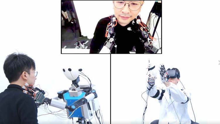
Figures 1 and 2 show the configuration and the general view of the TELESAR VI system, respectively. This system is a master-slave system consisting of a visuoauditory information system, where visuoauditory information is measured, transmitted, and presented in real-time to the operator; the movement measurement and control system, where the operator's movement is measured and transmitted in real-time to control the robot such that its movement tracks that of the operator, and the haptic information system, where haptic information is measured, transmitted, and presented to the operator in real-time.
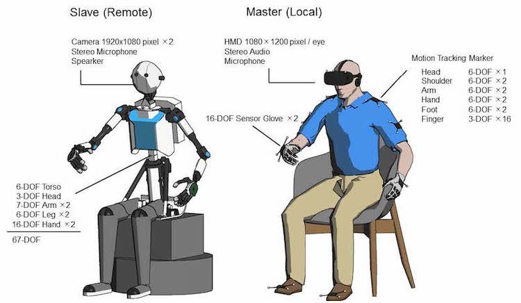
Figure 1: System diagram of TELESAR VI.
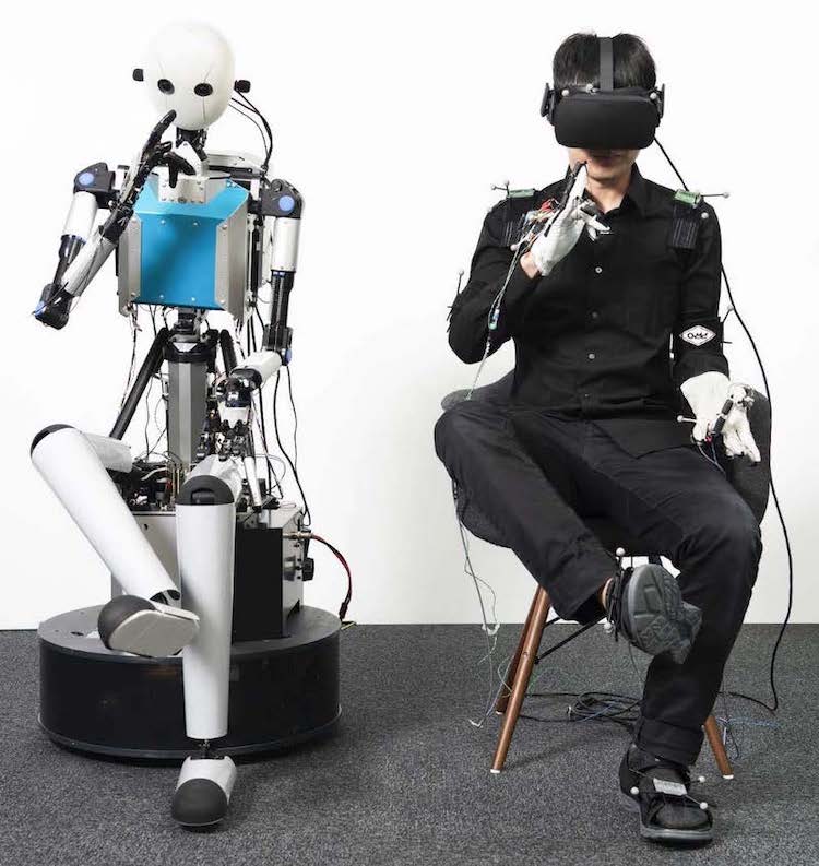
Figure 2: TELESAR VI master slave system.
The details of the TELESAR VI system are described in Secs. 3–4.
| 1. Introduction | 2. An Overview of TELESAR VI | 3. Mechanical Specifications of TELESAR VI |
| 4. Master-Slave Control System of TELESAR VI | 5. Principle of Haptic Primary Colors |
| 6. Haptic Telexistence for TELESAR VI | 7. Feasibility Experiments (Demonstration) | 8. Conclusion | References |
3. Mechanical Specifications of TELESAR VI
3.1. Overall Configuration
As briefly described in the previous section, the mechanism of TELESAR VI consists of several body parts: a main body consisting of 6DOF torso and 3DOF head, a pair of 7DOF arms attached to the shoulder of the main body, a pair of 6DOF legs attached to the bottom of the main body, and a pair of 16DOF hands attached to the top of the arm. The joints in the mechanism are equipped with high-power DC micromotors (FAULHABER Drive Systems) and have a wide movable range, sufficient to replicate the human body movement. The details of each part are described in the following subsections.
3.2. 6DOF Torso and 3DOF Head
Figure 3 shows the outline of the main robot body consisting of 6DOF torso and 3DOF head, and Table 1 shows the specifications. The hip is equipped with a lightweight parallel actuator to drive its joints (JB1 and JB2) to achieve quick body movements. In addition, the spine is equipped with a linear actuator to move the body vertically to maintain head height against body sway. If the rotation mechanism is applied to the vertical adjustment, the torso would spread out horizontally when it was lowered. By using the linear actuator in the spine, the body structure of the torso becomes closer to actual human body.
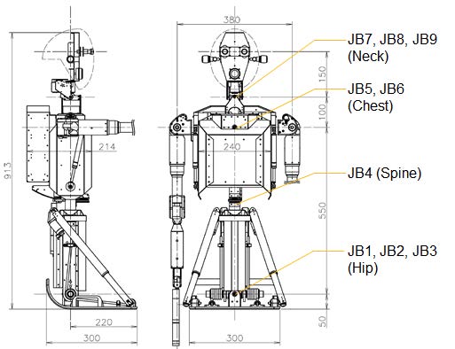
Figure 3: Outline drawing of the main robot body.
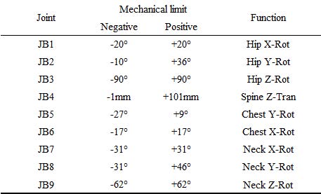
Table 1: Specifications of the body joints.
3.3. 7-DOF Arms
Figure 4 shows the outline of the 7DOF robot arm, and Table 2 shows the specifications. This size, motion range, and DOF configuration of the robot arm are the same as those of an actual human body. The maximum payload of 1kgf is achieved using the lightweight robot mechanism, which weighs approximately 2 kgf.
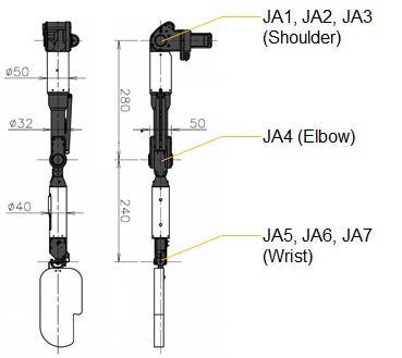
Figure 4: Outline drawing of the robot arm.
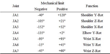
Table 2: Specifications of the arm joints.
3.4. 6-DOF Legs
Figure 5 shows the outline of the 6DOF robot leg, and Table 3 shows the specifications. As with the arm, the size, motion range, and DOF configuration of the robot leg are similar to those of a human body. Although the legs cannot support the upper body and cannot be used to walk, they, however, possess motor abilities like knee raising at 60 deg/s and kicking at 180 deg/s, thereby reproducing the natural leg motion of a human sitting on the chair.
Figure 5: Outline drawing of the robot leg.
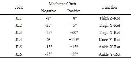
Table 3: Specifications the leg joints.
3.5. 16-DOF Hands
Figure 6 shows the outline of the 16DOF robot hand, Fig.7 shows the kinematical arrangement of the finger joints, and Table 4 shows the specifications. The joint arrangements of the four fingers (II–V) are common, and thumb (I) only have different arrangement. According to the movability, each finger is assigned different DOFs (thumb(I): 5, index(II):3, middle(III): 3, ring(IV):2, little(V): 2). The thumb has a wide range of motion, and its tip can be directed to the other fingers. This is incorporated to realize finger opposition, which is the main feature of human hand. In addition, the directions of index, ring, and little fingers can be changed simultaneously using an abduction joint.
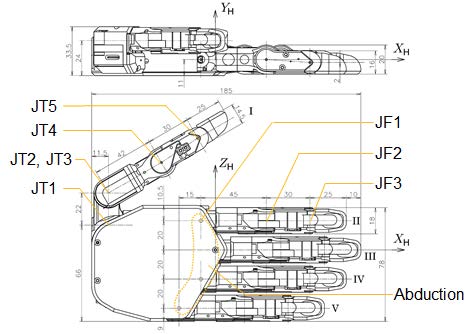
Figure 6: Outline drawing of the robot hand.
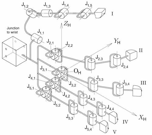
Figure 7: Kinematical arrangement of the finger joints.
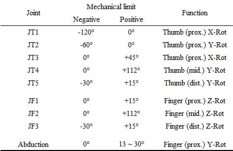
Table 4: Specifications of the thumb and finger joints.
| 1. Introduction | 2. An Overview of TELESAR VI | 3. Mechanical Specifications of TELESAR VI |
| 4. Master-Slave Control System of TELESAR VI | 5. Principle of Haptic Primary Colors |
| 6. Haptic Telexistence for TELESAR VI | 7. Feasibility Experiments (Demonstration) | 8. Conclusion | References |
4. Master-Slave Control System of TELESAR VI
4.1. Control Principle of Telexistence Robot
To realize the telexistence robot, the master-slave control system must be endowed with certain functions to achieve a sensori-motor consistency between the human operator and surrogate robot. Since the size and degrees of freedom of the human and robot bodies are different, even if the angles of each joint are identical, the robot will not be able to move as expected. What is important is to control the vector from the camera to the hand of the robot so that it matches the vector from the human eye to the hand. The same is true in controlling the fingers. TELESAR VI focuses on the vectors between the thumb and the other fingers, and devising and introducing a new control method to make them coincide in master and slave (Figure 20).
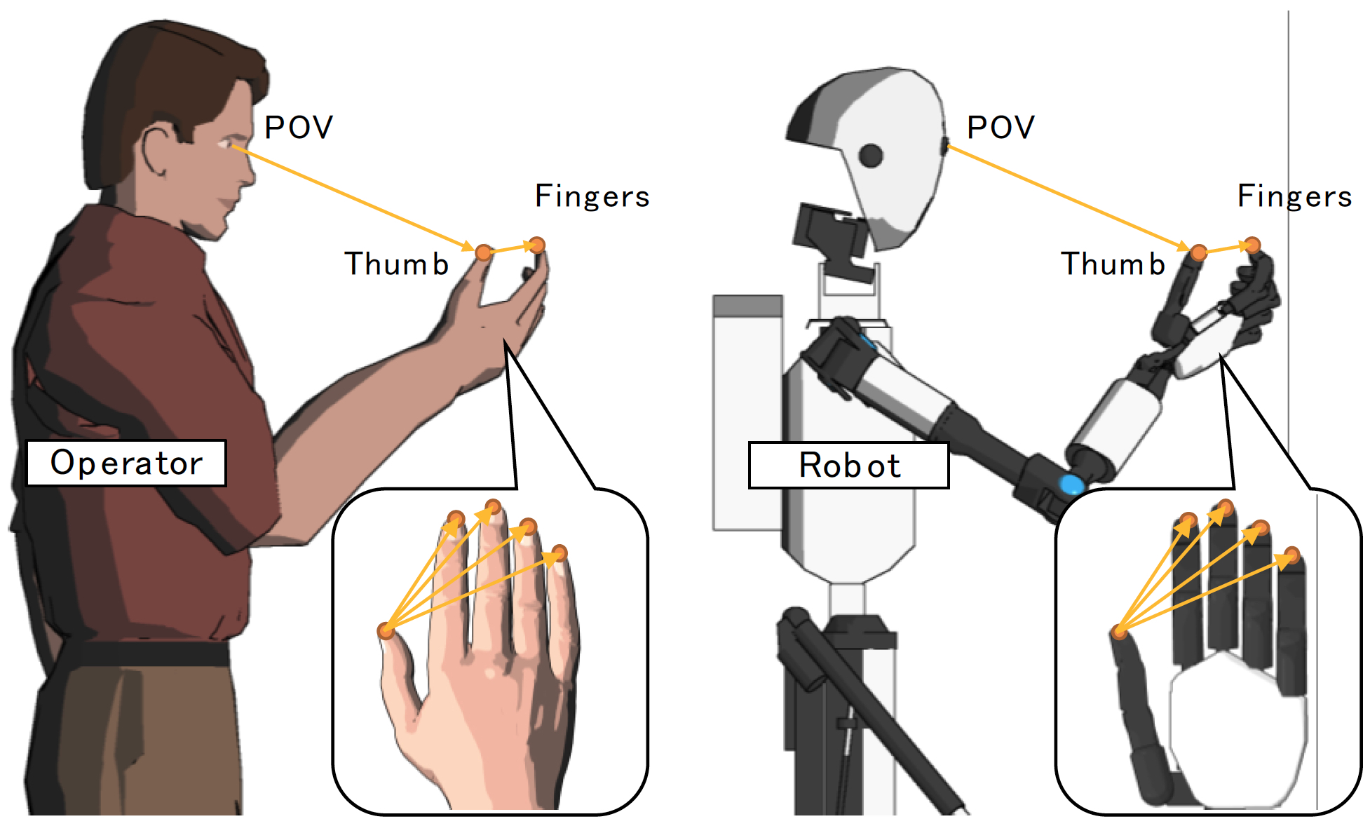
Figure 8: Congruence of POV to thumb/finger vectors between operator and robot.
According to the above discussion and previous studies regarding telexistence [19], it is important to keep the operator’s eye-to-arm endpoint vector equal to that of the robot so that the operator can always see the robot’s end effectors such as hand and fingers like as his/her own body. These conditions are formularized by the following two equations:
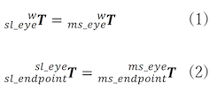
where  is a 4x4 homogeneous transform matrix, which describes the position and rotation of frame B relative to A. Eq. (1) exactly tracks the head motion, whereas Eq. (2) ensures the consistency of position and attitude of end effectors observed from the camera view. Based on this formulation, the kinematic equations are derived to realize the master-slave correspondence of each body-part. Detailed expressions are shown in the following section.
4.2. Motion Generation of Slave Robot
4.2.1. Torso and Head Control
As aforementioned, it is crucial to reproduce the operator’s head motion onto the robot’s head to realize the telexistence. This is because the operator of telexistence robot observes the point-of-view (POV) image shot from robot’s eye camera. Therefore, 6DOF head tracking is necessary to provide an immersive experience to the operator.
Based on Eq. (1), the kinematic equations of the robot’s main body can be derived and solved to realize the head tracking. The right-hand side of Eq. (1) can be determined by measuring the operator’s head position and attitude, whereas the left-hand side can be expanded by calculating the forward kinematics of TELESAR VI. However, the expressions on the left-hand side contain nine kinematic parameters because of 9DOF even though the head position and attitude are fulfilled by 6DOF. Therefore, additional constraints regarding operator’s body motion are necessary to obtain a unique solution of the head tracking. In most cases, the operator’s chest position and direction can be used to determine the equations.
4.2.2. Arm and Leg Control
Another major requirement of telexistence is to place the robot’s end effector at the location where operator’s corresponding body-part exists relative to the POV. This is because the operator should be able to see the end effector instead of his/her own body-part at the location where the actual part exists to maintain the visuo-somatosensory consistency regarding the body consciousness. Therefore, arm and leg control must be performed only after achieving torso and head control.
For the 7DOF arm, the kinematic equations are derived from Eq. (2), and these are solved to set the end effector (i.e., hand) at the position and attitude same as those of the operator. However, an additional constraint is required to determine the seven parameters of arm kinematics. In most cases, the direction of operator’s upper arm can be used for the constraint.
In addition, the kinematic equations of the 6DOF leg are derived in a manner similar to those of the arm, and they can be solved using the operator’s toe position and attitude. In the case of leg, additional constraint is not required because the number of kinematic parameters is equivalent to 6DOF.
4.2.3. Thumb and Finger Control
Similar to the arm and leg, the fingers of the robot hand are controlled based on Eq. (2) to maintain the same eye-to-endpoint vector. However, although Eq. (2) should be satisfied for all fingers, it is quite difficult to obtain an ideal matching because the anthropomorphic robot finger has only 2–5 DOF while a 6DOF is required for each finger to completely satisfy the equation. In addition, even if some elaborate robotic finger had more than 6DOF, the finger length difference between operator and robot leads to different hand postures. Therefore, it is necessary to compromise certain factors.
Considering that the thumb plays a crucial role in hand manipulation and is the most flexible among the five fingers, the position and direction of robot’s thumb tip must be controlled with high accuracy. In contrast, assuming that the reproduction of finger opposition is achieved only by the positional matching of the fingertips, the other four opposite fingers have to simply follow the positions of the endpoints of operator’s fingertips relative to the thumb tip to mimic the operator’s hand manipulation. These conditions result in two different kinematic equations as shown below:
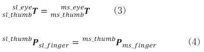
where  is a 4x1 position vector of point B relative to frame A. Eq. (3) and (4) imply that the polygonal chain of vectors connected to POV, thumb, and other fingers is a congruence between the operator and robot [20]. Figure 8 shows the schema of the congruence of vectors in the method. As long as the finger opposition is reproduced correctly, the operator can see and control the robotic fingers as perfect as his/her own fingers. Also, to realize this, the width of field of view (FOV) between them have to be corresponded exactly so that the camera image shoot in specific visual angle is projected on the operator's retina in the same way. In the visuoauditory information system of TELESAR VI, the angle of view of the eye-camera (See3CAM-CU135, e-con Systems) is adjusted to H: 90deg/V: 50deg per eye, and the camera images are stereoscopically presented to the operator's eyes by using a head-mounted display (Oculus CV1, Oculus Inc.) with keeping the FOV of eye-camera. In this way, the direction of light received on the robot's camera is correctly reproduced on the operator's sight.
4.3. Motion Measurement of Master Operator
To realize the master-slave control of telexistence robot, the body motion measurement of the operator should be as precise as the robot control because the motion data are used to calculate the target values of the controller. This section describes the details of motion measurement system of the master.
4.3.1. Optical Motion Measurement
To obtain the operator’s body motion in real time, an optical motion capturing system (OptiTrack, NaturalPoint, Inc.) consisting of eight cameras surrounding the operator’s whole body is employed as the measurement system. Through this system, 6DOF position and attitude data of operator’s nine body-parts (head, shoulders, arms, hands, and feet) are recorded using the retroreflective makers attached on the parts at a sample rate of 240 Hz. These data are employed for the motion control of slave robot’s body-parts such as head and arm-endpoints. In addition, the active maker sensor, which tracks the position using LEDs, is installed in the system, and the makers are attached to the fingertips of the operator to obtain 3DOF position data. These data are employed for the motion control of slave robot’s corresponding fingers in terms of the fingertip position. Moreover, these data are used to learn the data of position estimation method described later.
4.3.2. Wearable Measurement Device
In addition to the aforementioned motion capture system, a wearable sensor glove (IGS-Cobra Glove 16, Synertial UK Ltd.), which is equipped with 16 inertial measurement units (IMUs) is employed to obtain operator’s finger motion in detail. This sensor glove measures 3DOF attitude data of operator’s finger segments at a sample rate of 60 Hz, and these data are employed for the motion control of corresponding robot fingers in terms of the fingertip orientation. In addition, these finger segment data are used to excite the estimation method described later.
4.3.3. Fingertip Position Estimation
To achieve natural teleoperation using telexistence robot, the motion measurement of operator should be precise and stable to reproduce the operator’s body action, particularly hand manipulation. Therefore, the measurement system is endowed with two different finger measurement sensors. However, the stability of position tracking is still insufficient to achieve precise manipulation because of the limitation of optical measurement such as occlusion. If the fingertip position of the operator is lost, the finger motion of the robot becomes confusing. To overcome this problem, a data complement method of fingertip position is developed [21]. This method is based on the forward kinematics model of human hand, which represents the operator’s finger motion, and the estimated position of fingertip can be calculated using sensor glove instead of motion capture system. Provided that this method needs advanced calibration of the internal model parameters with the learning data of motion capture. Figure 9 shows the time series of estimated fingertip positions. As shown in the figure, the accuracy of the position estimation is considerably high, and the root mean square error (RMSE) of the data is on average 5.2 mm. Note that the accuracy depends on the quality of kinematics model whose parameters are estimated from the learning data.
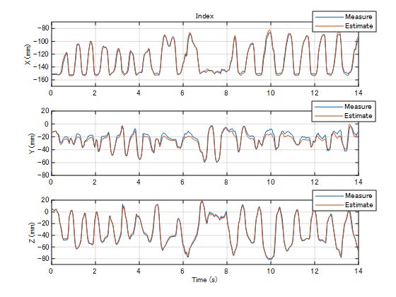
Figure 9: Estimated fingertip position versus actual measurement data.
4.4. Evaluation of Correspondence between Master-Slave Movement
4.4.1. Trackability of head motion
In order to keep master's POV position and direction identical with the slave's ones, the tracking ability of head motion is important factor for telexistence robot. To evaluate the tracking ability of head movement, the responsiveness of single-axis rotation of 3DOF head is analyzed at first. Figure 10 shows the rotation angle for each axis obtained when the operator shaken his head quickly without body movement and slave followed the movement. As shown these graphs, there are slight delay between them, and the cross-correlation function was calculated to evaluate the temporal delay for each axis. As the result, the delay in roll-, pitch-, and yaw-axis are 67 ms, 92 ms, 83 ms, respectively. These values are adequately low enough to track the POV direction of operator's head movement without discomfort.
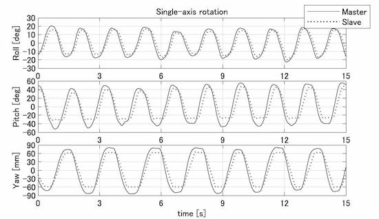
Figure 10: Single-axis rotations of head motion.
4.4.2. Error in Head Motion Trajectory
In addition to single-axis head rotation, to evaluate the positional accuracy of reproduced head motion the operator's POV during the actual operation including body movement, the cross-correlation function of head motion trajectory in 3D space between operator and robot is analyzed. Figure 11 shows the time series of head motions obtained when the operator repeatedly and laterally swayed his upper body with neck motion and the robot followed the movement. Same as the result of head rotation angles, temporal delay of the motion trajectory is observed between them, but the cross-correlation function between them revealed that the delay was approximately 340 ms. This value is greater than the delay of single-axis head rotation shown above. It is because the body movement produces more inertia of upper body in comparison to single head movement, leading large temporal delay. Note that this quick and repeating movement examined here is an extreme example to evaluate the responsiveness of mechanical system in upper-body. In normal, the body moves more slowly, therefore the delay has small effect. Rather, the accuracy of position is more important factor. Therefore, the positional errors at the turning points of motion trajectory were evaluated. For twelve pairs of corresponding peaks, the positional error was 19±8 mm. This means reproduced POV position of slave robot is adequately accurate even though the operator moves fast.
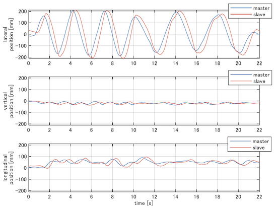
Figure 11: Head motion trajectories of master operator and slave robot
4.4.3. Error in Hand Motion Trajectory
Same as the head motion analysis, the reproduction accuracy of end-effector in 3D space is evaluated using the cross-correlation analysis. Figure 12 shows the time series of hand motions obtained when the operator repeatedly and vertically shook his right hand without any other body motion and the robot followed the movement. Similar to the head motion results, a slight temporal delay is observed between them, and the cross-correlation function between them revealed that the delay was approximately 160 ms. This value is faster than the delay in head position, but close to the delay in head rotation. During robot hand manipulation in telexistence, it is expected that head position does not move so extensively whereas the head direction does changes frequently. Therefore, the delay is appropriate. Also, positional errors at the turning points of motion trajectory were evaluated same as head motion.
For twelve pairs of corresponding peaks, the positional error was 59±11 mm. The spatial divergence of hand position can lead misdirection of the vector to the fingers, and the positional error observed here is not small. However, it can be probable improved by gain adjustment of the 7DOF arm, because the many amounts of the error come from undershoot of vertical axis, that is caused by the less elevation of arm movement.
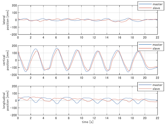
Figure 12: Hand motion trajectories of master operator and slave robot
| 1. Introduction | 2. An Overview of TELESAR VI | 3. Mechanical Specifications of TELESAR VI |
| 4. Master-Slave Control System of TELESAR VI | 5. Principle of Haptic Primary Colors |
| 6. Haptic Telexistence for TELESAR VI | 7. Feasibility Experiments (Demonstration) | 8. Conclusion | References |
5. Principle of Haptic Primary Colors
To convey the same sensation felt when a person touches the surface of a physical body with his or her finger, if it is necessary to present the same actual physical body to the finger, the sense of touch cannot be handled as information media. In the case of vision, even if the color of a physical body differs from the actual spectra, if the cone cells on the human retina responsible for human RGB ranges are in the same proportions, the object appears to have an identical color. This very principle makes TV, color photographs, and color prints possible. It is the principle of three primary colors. The principle of haptic primary colors argues that the same principle holds for the sense of touch. In other words, it assumes the existence of haptic primary colors.
One evidence for the existence of haptic primary colors is the presence of distinctly different types of sensory receptors. They include Merkel cells, Meissner’s corpuscles, Pacinian corpuscles, and Ruffini endings. There are also free nerve endings that respond to heat, cold, and pain. Neurophysiological research reveals that Merkel cells and Ruffini endings detect pressure and shearing forces, Meissner’s corpuscles detect low-frequency vibrations, and Pacinian corpuscles detect high-frequency vibrations. Furthermore, it is assumed that, when the skin comes into contact with a physical body, Merkel cells and Ruffini endings detect displacement, Meissner’s corpuscles detect velocity, and Pacinian corpuscles detect acceleration at the contact to the physical body.
Real physical bodies have many physical properties, such as concavo-convex shape, friction, heat, and elasticity. To reproduce all these properties requires bringing in the object itself, and it is impossible to present them through information media. However, if we consider situations in which a cutaneous sensation arises, we know that when a person touches an object, force, vibration, and temperature change occur on the skin surface, which triggers responses from the aforementioned sensory organs, giving rise to the sensation of touch. If this is the case, regardless of what the physical properties, such as concavo-convex shape, friction, heat and elasticity, are, if sensory receptors respond in the same manner as when the person touches the physical body, the same sense of touch arises in him/her.
Therefore, haptic primary colors can be determined by selecting primary variables in the physical space based on the method equivalent to the method of visual perception in which RGB are the primary variables. Merkel cells and Ruffini endings respond to pressure and shearing force, Meissner’s corpuscles to low-frequency vibrations, Pacinian corpuscles to high-frequency vibrations, and free nerve endings to pain, heat and cold, and pressure. Therefore, even when a person is not actually touching a physical body, if the same pressure and shearing force, that is, “force” as a vector, the same “vibrations”, from low to high frequencies, and the same “temperature” as those presented on the surface of the human skin when touching a genuine physical body are presented, the person will have the same sensation. Although sensations change with the active movements of the person, we need only to track these movements to faithfully reproduce them.
This approach is akin to the approach to visual perception, which, instead of reproducing all spectra of light, uses only those spectra that correspond to RGB and reproduces almost all visual information based on the combination of these primary variables.
Thus, the current approach uses three physical quantities—force, vibration, and temperature—as primary variables, which arise when the skin surface comes in contact with a physical body, and records and transmits their changes over time. Subsequently, it synthesizes various sensations of touch based on these variables, instead of reproducing all the aforementioned physical properties of the physical body. Figure 13 shows the principle of haptic primary colors in relation to primary variables in the physical, physiological, and psychological spaces [22,23].
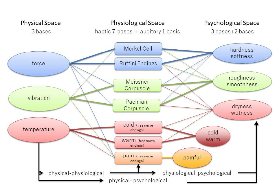
Fig. 13. Principle of haptic primary colors.
The aforementioned discussion can be summarized as follows:
A target object has physical properties, such as the concavo-convex shape, surface texture, friction, thermal conductivity, viscosity, elasticity, inertia, and humidity. However, generally, human cutaneous receptors only sense force (skin deformation), vibration, and temperature change, which occur at the contact to the physical body when the person touches the target object. Therefore, the optimal sensors are the force, vibration, and temperature sensors that directly sense these quantities. These quantities are transmitted and presented to the person through the force display, vibration display, and temperature display. Figure 14 shows the diagram of the measurement system, transmission, and presentation based on the principle of haptic primary colors.
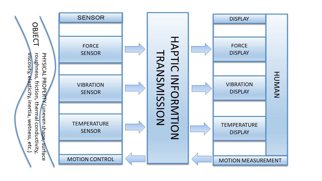
Figure 14: Haptic sensing, transmission, and display.
The following section provides a detailed explanation on the TELESAR VI hepatic transmission system based on the principle of the haptic primary colors.
| 1. Introduction | 2. An Overview of TELESAR VI | 3. Mechanical Specifications of TELESAR VI |
| 4. Master-Slave Control System of TELESAR VI | 5. Principle of Haptic Primary Colors |
| 6. Haptic Telexistence for TELESAR VI | 7. Feasibility Experiments (Demonstration) | 8. Conclusion | References |
6. Haptic Telexistence for TELESAR VI
6.1. Haptic Sensing System for a Slave Hand
A haptic sensing system, equipped with sensors for the haptic primary colors (force/ vibration/temperature), 32 was developed for the hand of robot TELESAR VI. The haptic control board was mounted on the back of the robot's hand (Figures. 15 and 16). The haptic control board has parallel wired connections to each finger-tip sensor board using the I2C protocol. The weight of the developed slave hand is 0.562 kgf. The haptic sensors are embedded in the finger-tip structure (Figure 17). The acceleration sensor and thermistor are soldered onto the finger sensor board. The thermistor (56A1002-C3, Alpha Technics) is connected via an analog-to-digital converter (ADC) module (ADS1015, 12 bit, 4 ch.). The ADC quantizes the resistance of the thermistor and transmits the voltage via I2C. The sensor board has a wired connection to the finger base board, along with the force-sensor connection. The haptic information is transmitted between the finger-tip base board and the haptic control board.
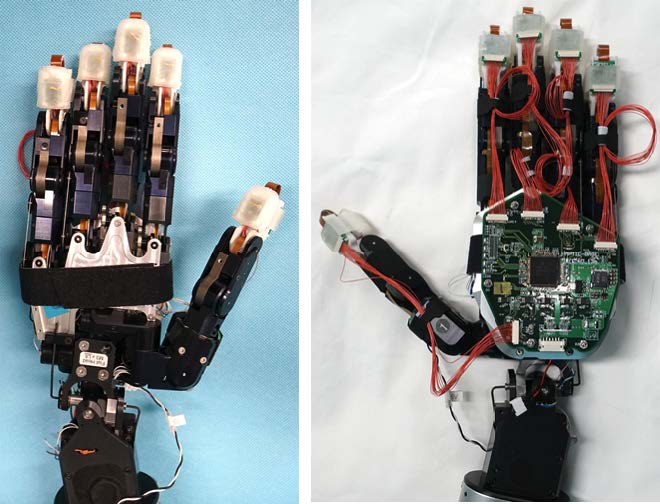
Figure 15: Slave hand with haptic sensors for each finger.
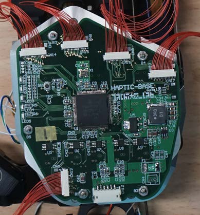
Figure 16: Haptic base board.
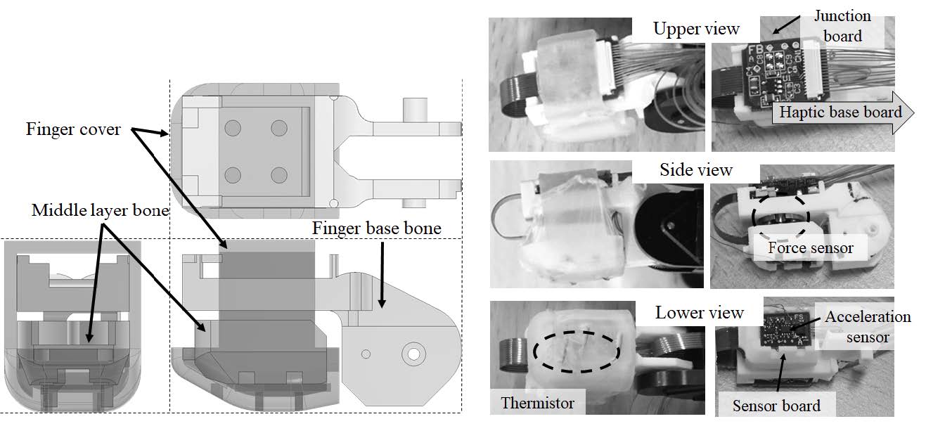
Figure 17: Finger-tip structure (left: engineering drawing; right: developed haptic sensors).
To acquire the acceleration, a KX126-1063 3-DOF accelerometer was embedded in the finger-tip (the read rate/gravity range/quantum bit are 1.6 kHz/2 g/12 bit, respectively; Kionix/ROHM Semiconductor Co., Ltd.). A piezoresistance 3-DOF force sensor (μDynPick MAF-3, 1 kHz, WACOH-TECH Inc.) was used to acquire the vertical force and the two horizontal-force components. The haptic information from the five fingers was transmitted to the haptic control board in parallel, using separate I2C ports.
The measured haptic signal was transmitted to a PC through an Ethernet cable. The waveform of the haptic information was displayed on the PC, and then re-compounded for presentation using the haptic display on the master glove.
Figure 18 shows a diagram of the haptic signal transmission and some waveform examples acquired by the haptic primary-color sensors.
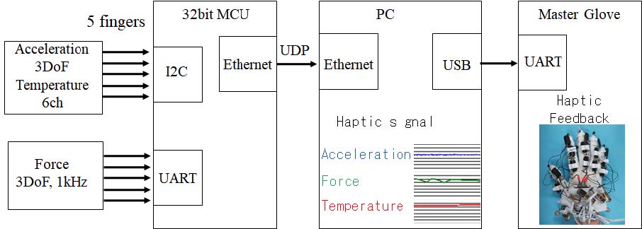
Figure 18: Haptic signal transfer to the master glove.
6.2. Finger Design Configuration
In this section, the haptic finger design is described. The haptic sensors and boards were embedded in the finger structure. A relay board was mounted on top of the finger base bone (Figure 17), and the force sensor was fixed under the bone. The finger base bone was connected to the first knuckle joint. The middle layer bone was bridged by the force sensor (the opposite side). The finger sensor board was equipped at the bottom of the middle layer bone. The thermistors were located on the exterior surface of the finger cover.
The lead wire of the thermistor was soldered onto the sensor board. The thermistor location acted as a type of contact sensor because several thermistors were distributed on the finger cover. The temperature fluctuation allowed the location to detect a grabbed object on the finger pad. The thermistor was fixed using a thin high-expansion elastic film (0.01 mm, moist healing pad, Hakujuji Co., Ltd.) on the finger cover.
Artificial skin, made from elastic urethane resin and aluminum oxide powder, was investigated. The aluminum oxide was expected to improve the heat conduction to the thermistor. Figure 19 (lower) shows the skin attached to the finger cover. The trial manufactured skin was used as a telemedicine module that reproduced the human body temperature [24], and the thermal conduction from the device improved its performance over that of rubber. Despite the good heat conduction, the proposed artificial skin was much thicker (nearly 1mm) than the thin film (0.01mm, Fig. 19(upper)). Second, the compounded skin was very sticky, and was covered with talc powder to reduce the stickiness. The talc powder could affect the robot's electronic circuits or mechanism. Therefore, we chose thin film for the demonstration experiment.
The finger-structure parts were 3D printed; the finger base bone and middle layer were printed using solid-light nylon material, and the finger cover (Figure 17) was printed with soft silicon rubber (AGILISTA (AR-G1L), shore stiffness 35). The soft silicon rubber was used to enable the finger to easily grab an object. The proposed fingers have a significantly improved grasping ability compared to the previous robot fingers with hard finger pads [19].
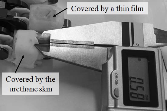
Figure 19: Ultra-thin elastic film (upper finger); compounded urethane resin (lower finger).
6.3. Haptic Primary-color Display for a Master Glove
A master glove that could present the haptic primary colors was proposed. To display the measured haptics information, a vibro-thermal presentation module and an encounter-type force-presentation system that was driven by a thread were embedded in the glove (Figure 20). Both modules were mounted on top of each glove finger. These tactile modules composed the haptic primary color texture. We introduce the force-presentation system and vibro-thermal module.
A finger-posture acquisition system comprised the master glove (Figure 20). Since an infrared (IR) LED marker (active-tracking type) was mounted at each finger-tip of the glove, the posture of the finger end was obtained at 30 Hz using optical motion capture. Second, inertia sensors (AiQ Synertial Ltd., IGSCobraGlove16) were mounted on the glove over the phalanges, enabling them to measure the phalange posture [25].
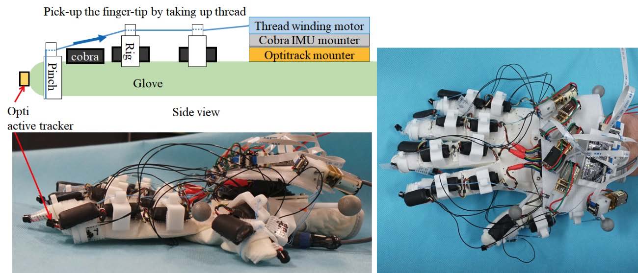
Figure 20: Encounter-type haptic display mounted on the master glove.
6.4. Force Presentation by Gel Pad
We designed and developed a wearable deep-sensory presentation device [26,27] that stimulates deep sensation in the finger joints. Figure 21 shows how a deep-sense presentation device is attached to a finger.
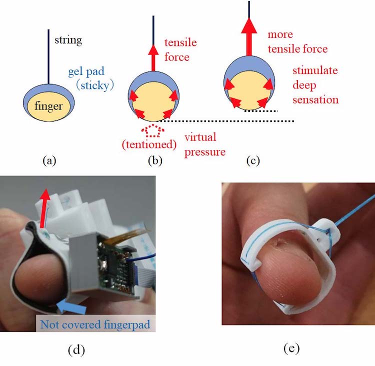
Figure 21: Force presentation mechanism by sticky gel-pad and thread.
We describe our proposed haptic device that stimulates deep sensation. To apply force, a sticky gel pad is attached to a fingertip. When a thread sewn to the gel pad is drawn by motor force, it initially deforms the fingers. It then stimulates a deep sensation inside the finger joint by applying additional force. The gel pad is worn around a finger, covering the sides and the top. When a thread is pulled up, as shown in Figures 21(b) and 21(c), the skin of the side finger is also pulled up. It applies tension, which feels like a virtual force, to the finger-pad. When the force increases beyond the skin deformation range, the fingertip is pulled up, stimulating a deep sensation. Thus, a continuous force presentation, from skin deformation (tactile) to deep sensation (haptic), is enabled.
To realize the continuous-force presentation, the proposed device consists of a gel pad, a thread, a thread-passing column, and a DC motor for winding the thread. The system configuration diagram is shown in Figure 22.
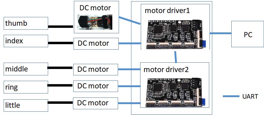
Figure 22: Motor control configuration of the thread-driving system.
The gel pad covers both sides of the fingertip and the fingernail without covering the finger-pad (Figure 21(d)). A thread is sewn to the gel pad attached to the fingernail. The other end of the thread is wound by a pulley attached to a motor, mounted on the back of the hand. On the path to the fingertips, the thread passes through a threading column mounted on the gel pad. The threading column was designed by CAD, according to the shape of the finger, and printed with nylon material. A small DC motor (Micro Metal Geared motor, HP 6V, gear ratio 10:1, Pololu Robotics & Electronics) [28] with back drivability was used to drive.
6.5. Force Presentation to pick up the Finger
We propose a finger pick-up-type force-presentation system that is driven by a thread. In the previous section, we described a force-presentation method using a sticky gel-pad. It can be used to apply force from tactile (skin deformation) to deep sensation. However, the gel-pad has some defects; for example, the stickiness decreases from sweat, usage count, etc. Therefore, a pick-up-type force-presentation system was proposed, with a similar mechanism.
The former mechanism has rolls to keep the adhesive between the finger back and sides and the gel-pad. When the gel-pad is pulled up by the thread, it also pulls up the sides of the finger. An elastic ring in the shape of a C was used to pick up the finger from both sides. Figure 21(e) shows the ring placed on the finger. Figure 20 lower picture shows the developed master glove.
The proposed method enables a robust application of force, despite wet or sweaty conditions. It enables a continuous force presentation from weak (skin deformation) to strong (deep sensation). The pick-up ring pushes both sides of the finger-pad bottom, unlike the gel-pad method, which pulls up both finger sides, and expends the virtual force on a finger-pad. The ring method could conceivably improve the adhesion to both sides of the finger.
6.6. System Configuration
Figure 22 shows the driver board (PIC32 MM0064 GPL036). It sends a command from the PC via UART (asynchronous serial communication) to control the motor. In response to a command from the PC, the control target is obtained, the sensor information is returned, and the motor is controlled.
Since a magnet is attached to the pulley, the rotation can be measured. Moreover, position control is possible by controlling the rotational speed of the pulley. In addition, both motor drivers (DRV8833, Texas Instruments) have a current-measurement function that can perform pulse-width modulation (PWM) control of up to 10.8V and 1.5A for two circuits. A No. 0.8 (4.8 kgf) thread thickness was used. Because of safety considerations, the force that human fingers can exert is estimated to be about 5 kgf.
6.7. Composition of the Haptic Primary-Colors Presentation Glove
By combining the vibro-thermal tactile unit (Figure 23) [29,30] with a glove (Figure 21(d)) capable of presenting tactile force and deep sensation, it becomes possible to present the three haptic primary colors of force, vibration, and temperature. The vibrothermal tactile unit was developed by the JST ACCEL project on \Embodied Media Technology based on Haptic Primary Colors." A compact version of the vibrating actuator (ForcereactorTM AF series) provided by ALPS ELECTRIC Co., Ltd. Is embedded inside the device. A Peltier element (KSMH029F, KELK Ltd.) [31] is mounted on the top of the device. A haptic presentation corresponding to the tactile primary colors is possible. The weight of the developed master glove is 0.313 kgf.
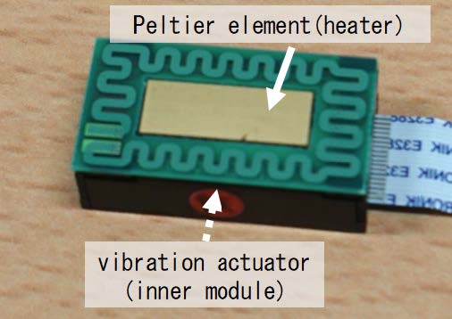
Figure 23: Vibro-thermal tactile module.
6.7.1. Haptic sensor evaluation
Figure 24 shows examples of the haptic signal acquired from the proposed system. Data from different type of woven cloths (plain weave, acrylic fur, and denim) were acquired. Acceleration (vertical), force (vertical), and temperature signals from an index finger were measured for one second. Lower right chart of Figure 24 shows the signal example acquired by rubbing a cucumber surface which has just been taken out from a refrigerator. When the robot finger touched convex part of surface, a lower temperature was measured.
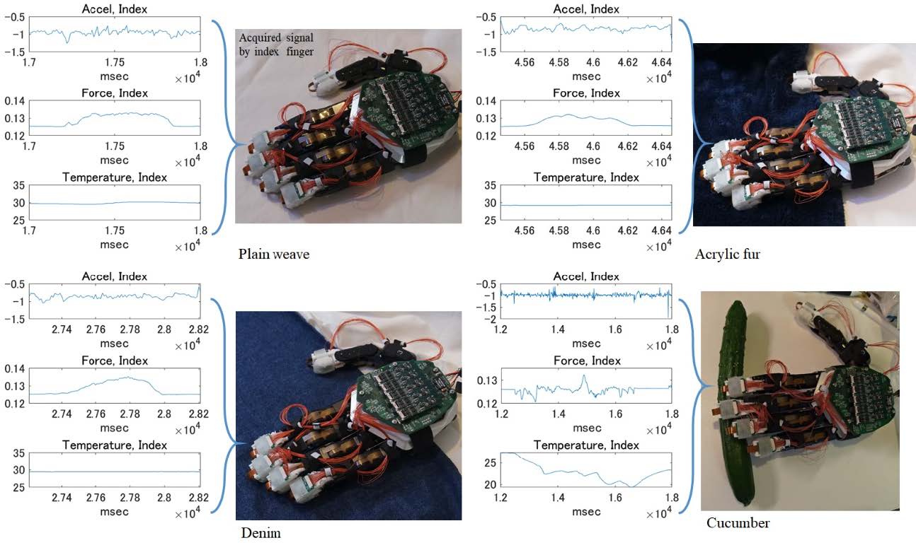
Figure 24: Haptic primary color data for three cloths (plain weave, acrylic fur, and denim) and cucumber.
The upper image of Fig. 25 shows the temperature data when the robot hand is grabbing a glass of hot black tea. Since the thumb, middle, and ring finger of the robot touched a glass with under the liquid level of the glass, rapid increases in temperature were observed for these fingers. Since the thumb has more degree of freedom and particularly fits the surface of the glass, the more rapid rising in temperature was observed. Gentle temperature increase was observed for the index finger, which touches the glass above the liquid level. The little finger did not touch the glass firmly, so the temperature rise was fairly gradual. The lower image of Figure25 shows the temperature data when the robot hand is grabbing a glass of iced black tea. Since the thumb, index, middle and ring finger of the robot touched a glass with under the liquid level of the glass, rapid decreases in temperature were observed for these fingers. Since the thumb has a high degree of freedom and particularly fits the surface of the glass, the more rapid falling in temperature was observed. The little finger did not touch the glass firmly, so the temperature fall was fairly gradual.
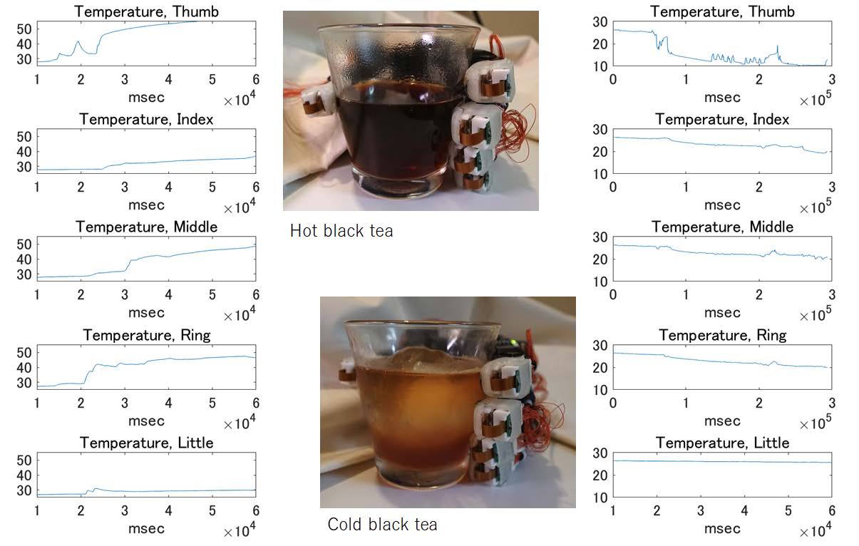
Figure 25: Grabbing hot/cold black tea.
6.7.2. Robustness of haptic display
The proposed haptic presentation glove is configured to fit both large and small hands of a wearer. The glove worn by the user has a module designed to fit the fingertip, which presents vibration and temperature (Figure 23) [30]. The pick-up ring (Figure 20) for presenting force to the fingertip has adjustability to the thickness of the user's finger. We adopted the mechanism that presents force by pulling a thread with a motor, so that the mounting position of the motor has high flexibility. The thread path and length from the motor to the fingertips can be adjusted to accommodate different hand and finger sizes. The motor can be worn not only on the back of the hand, but also on the arm. Therefore, our proposed method that can present a stable haptic sensation regardless of the wearer's hand size.
| 1. Introduction | 2. An Overview of TELESAR VI | 3. Mechanical Specifications of TELESAR VI |
| 4. Master-Slave Control System of TELESAR VI | 5. Principle of Haptic Primary Colors |
| 6. Haptic Telexistence for TELESAR VI | 7. Feasibility Experiments (Demonstration) | 8. Conclusion | References |
7. Feasibility Experiments (Demonstration)
In order to show the feasibility of TELESAR VI in the real world, demonstrations were conducted for four different situations. The demonstration video is open to the public.
Keyboard typing
Keyboard operation was chosen to show that all 10 fingers can be used. It enables the operator to type the keys with the same feeling as if he/she were typing with the finger remotely (Figure 26).
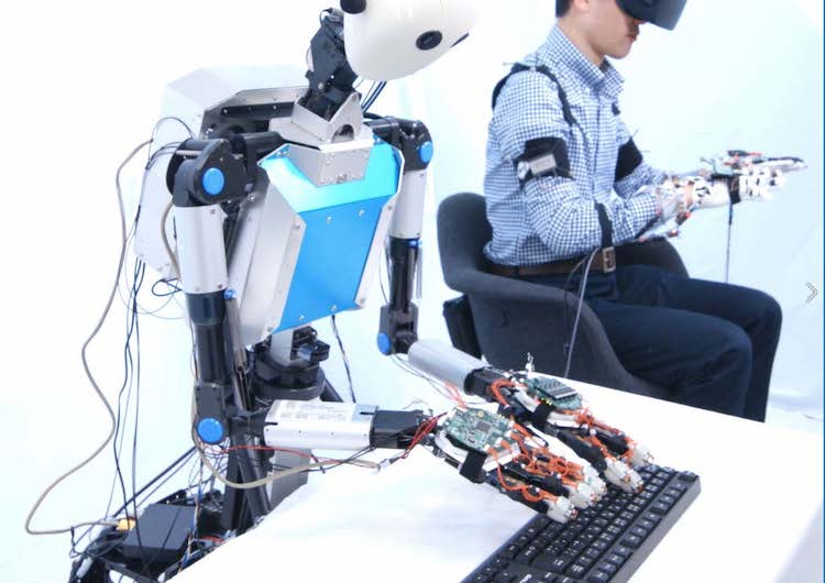
Figure 26: Typing HELLO.
Palpation
Palpation was chosen to demonstrate that TELESAR VI system can transmit tactile sensations using 10 fingers. There is currently an accelerated search for remote means of healthcare delivery in response to the new virus (COVID-19) around the world. One of the problems with current remote diagnosis is that it cannot convey tactile information while it can convey audiovisual information. We demonstrated the use of palpation to provide medical interviews/cares in such situations where direct medical treatment is a risk. It is supposed that a medical doctor touches the lymph nodes around throat and checks the body temperature when a patient complains about throat pain (Figure 27).
Figure 27: Tele-palpation for lymph node.
Trapping and shooting
The robot's operator can move freely while looking at the robot's legs as if they were his own legs. As a demonstration of how the whole-body coordinates including legs, the action of trapping and shooting a ball is chosen (Figure 28).
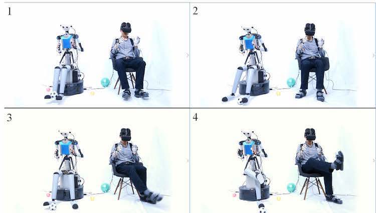
Figure 28. Trapping and shooting a ball.
Ikebana
As an example of performing delicate work using visual, auditory, and tactile senses, a demonstration was conducted by selecting Japanese fresh flowers including artistic aspects. Figure 29 shows the robot doing a Japanese-style flower arrangement. The avatar robot picked up a tulip stalk lying on a desk, moved the stalk above a tray and put it to a water-absorbing sponge base in the tray.
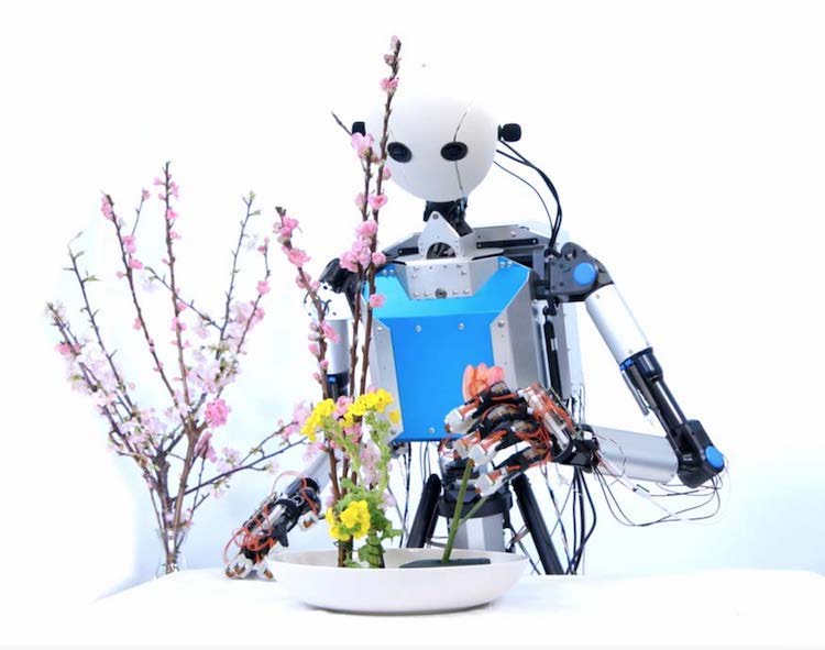
Figure 29. Ikebana-style flower arrangement.
| 1. Introduction | 2. An Overview of TELESAR VI | 3. Mechanical Specifications of TELESAR VI |
| 4. Master-Slave Control System of TELESAR VI | 5. Principle of Haptic Primary Colors |
| 6. Haptic Telexistence for TELESAR VI | 7. Feasibility Experiments (Demonstration) | 8. Conclusion | References |
8. Conclusion
In this paper, we described a telexistence avatar system, TELESAR VI. The novelties
of TELESAR VI are as follows:
(1) It is a telexistence robot which, unlike anything the world has ever seen, has 67 DOFs as an avatar, and can naturally convey and express various human actions.
(2) All of the ten fingers of the avatar robot are equipped with the force, acceleration (vibration), and temperature sensors and can faithfully transmit this haptic information. Thus, the combined use of the haptic and visuo-auditory information actualizes the remote sense of existence as if the operator were physically existing there as the avatar robot serves as a new body.
(3) It realizes novel control over fingers by equalizing the vectors between the thumb and other fingers in the master with those in the slave, thereby enabling accurate hand grasping.
In the future, we would like to apply this approach to remote work and telemedicine involving bodily movements, as well as telecommunication, and remote experience, such as traveling, shopping and entertainment industries.
| 1. Introduction | 2. An Overview of TELESAR VI | 3. Mechanical Specifications of TELESAR VI |
| 4. Master-Slave Control System of TELESAR VI | 5. Principle of Haptic Primary Colors |
| 6. Haptic Telexistence for TELESAR VI | 7. Feasibility Experiments (Demonstration) | 8. Conclusion | References |
References
1. S. Tachi, Telexistence, 2nd edn. (World Scientific, 2015), ISBN 978-981-4618-06-9.
2. A. Scoică, Susumu Tachi -the scientist who invented telexistence, ACM Crossroads 22(1) (2015) 61–62. [PDF]
3. S. Tachi, K. Tanie and K. Komoriya, Operation method of manipulators with sensory information display functions, Japanese Patent 1458263, filed 1981.1.11. [PDF]
4. S. Tachi and M. Abe, Study on Tele-existence (I), in Proc. 21st Annual Conf. of the Society of Instrument and Control Engineers (SICE) (Tokyo, Japan, 1982), pp. 167–168. [PDF]
5. S. Tachi, K. Tanie, K. Komoriya and M. Kaneko, Tele-Existence (I), in Proc. 5th Symp. Theory and Practice of Robots and Manipulators (RoManSy'84), Udine, Italy, 1984, pp. 245–254. [PDF]
6. S. Tachi, H. Arai, I. Morimoto and G. Seet, Feasibility experiments on a mobile telexistence system, in Proc. the Int. Symp. and Exposition on Robots, Sydney, Australia, 1988, pp. 625–636. [PDF]
7. S. Tachi and K. Yasuda, Evaluation experiments of a teleexistence manipulation system, Presence 3(1) (1994) 35–44. [PDF]
8. S. Tachi, K. Komoriya, K. Sawada, T. Nishiyama, T. Itoko, M. Kobayashi and K. Inoue, Telexistence cockpit for humanoid robot control, Adv. Robotics 17(3) (2003) 199–217. [PDF]
9. S. Tachi, Augmented Telexistence, Mixed Reality ___ Merging Real and Virtual Worlds, Y. Ohta and H. Tamura, ed. (Springer-Verlag, 1999), pp. 251–260. [PDF]
10. S. Tachi, N. Kawakami, M. Inami and Y. Zaitsu, Mutual telexistence system using retroreflective projection technology, Int. J. Humanoid Robot. 1(1) (2004) 45–64. [PDF]
11. S. Tachi, N. Kawakami, H. Nii, K. Watanabe and K. Minamizawa, TELEsarPHONE: Mutual telexistence master slave communication system based on retroreflective projection technology, SICE J. Cont. Measure. Syst. Integrat. 1(5) (2008) 335–344. [PDF]
12. K. Watanabe and S. Tachi, Verification of out of body sensations, attribution and localization by interaction with oneself, in Proc. of IEEE International Symp. Virtual Reality Innovations (ISVRI 2011), Singapore, 2011, pp. 111–118. [PDF]
13. S. Tachi, TWISTER: Immersive omnidirectional autostereoscopic 3D booth for mutual telexistence, in Proc. ASIAGRAPH 2007, Vol. 1, Tokyo, Japan, 2007, pp. 1–6. [PDF]
14. S. Tachi, K. Watanabe, K. Takeshita, K. Minamizawa, T. Yoshida and K. Sato, Mutual telexistence surrogate system: TELESAR4 -telexistence in real environments using autostereoscopic immersive display -, in Proc. IEEE/RSJ Int. Conf. Intelligent Robots and Systems, (San Francisco, USA, 2011), pp. 157–162. [PDF]
15. S. Tachi, K. Minamizawa, M. Furukawa and C. L. Fernando, Telexistence - from 1980 to 2012, in Proc. IEEE/RSJ Int. Conf. Intelligent Robots and Systems (IROS2012), (Vilamoura, Algarve, Portugal, 2012), pp. 5440–5441. [PDF] video
16. https://tachilab.org/en/accel_project.html.
17. S. Tachi, Forty years of telexistence - from concept to TELESAR VI, in Proc. Int. Conf. Artificial Reality and Telexistence and Eurographics Symp. Virtual Environments (ICAT-EGVE2019), (Tokyo, Japan, 2019), pp. 1–8. [PDF]
18. Y. Asano, K. Okada, and M. Inaba, Design principles of a human mimetic humanoid: Humanoid platform to study human intelligence and internal body system, Sci. Robot. 2 (13) (2017) eaaq0899.
19. C. L. Fernando, M. Furukawa, T. Kurogi, S. Kamuro, K. Sato, K. Minamizawa and S. Tachi, Design of TELESAR V for transferring bodily consciousness in telexistence, in Proc. IEEE/RSJ Int. Conf. Intelligent Robots and Systems (IROS2012) (Algarve, Portugal, 2012), pp. 5112–5118. [PDF]
20. Y. Inoue, F. Kato and S. Tachi, Master-Slave robot hand control method based on congruence of vectors for telexistence hand manipulation, in Proc. 22nd Int. Symp. Measurement and Control in Robotics (ISMCR2019) (Houston, USA, 2019), pp. A1-1-1-1–A1-1-1-4. [PDF]
21. Y. Inoue, F. Kato and S. Tachi, Finger Motion Measurement System for Telexistence Hand Manipulation, Proceedings of the 22nd International Symposium on Measurement and Control in Robotics (ISMCR2019) (Houston, USA, 2019), pp. C2-1-1–C2-1-4. [PDF]
22. S. Tachi, M. Nakatani, K. Sato, K. Minamizawa and H. Kajimoto, Tactile information conversion device, tactile information conversion method, tactile information conversion program, and element arrangement structure, United States Patents US 10,621,837 B2, filed Oct. 5, 2018. [PDF]
23. https://tachilab.org/en/about/hpc.html.
24. J. Fu, F. Kato, Y. Inoue and S. Tachi, Development of a Telediagnosis System using Telexistence, Trans. of the Virtual Reality Society of Japan, 25(3) (2020) pp.277-283. [PDF]
25. Y. Inoue, F. Kato and S. Tachi, Study on telexistence XCVII: full-body master-slave control of 67DOF telexistence robot including five-finger robot hand and leg mechanism, in Proc. 15th SIG-Telexistence (Tokyo, Japan, 2020), pp. 7–10. [PDF]
26. F. Kato, Y. Inoue, and S. Tachi, A haptic glove to display softness by stimulating deep sensation, IEEE World Haptics Conf. hands-on-demo, 2019, Tokyo, Japan, DM1.23.
27. F. Kato, Y. Inoue and S. Tachi, Haptic display glove capable of force/vibration/ temperature, in Proc. 22nd Int. Symp. Measurement and Control in Robotics (ISMCR2019) (Houston, USA, 2019), pp. D2–2–1–D2–2–5. [PDF]
28. Pololu Robotics & Electronics, available at https://www.pololu.com/product/999.
29. Tachi Lab - ACCEL Project, available at https://tachilab.org/en/accel_project.html.
30. M. Nakatani, K. Sato, K. Sato, Y. Kawana, D. Takai, K. Minamizawa and S. Tachi, A novel multimodal tactile module that can provide vibro-thermal feedback," Asia Haptics, Vol. 82F-1 (Kashiwa, Japan, 2016), pp. 437–443. [PDF]
31. “KELK Ltd," Available at http://www.kelk.co.jp/thermo/index.html.
32. F. Kato, Y. Inoue and S. Tachi, Soft finger-tip sensing probe based on haptic primary colors, in Proc. 28th Int. Conf. Artificial Reality and Telexistence 2018 (ICAT'18) (Limassol, Cyprus, 2018), pp. 107–114. [PDF]
33. TELESAR VI, Telexistence surrogate anthropomorphic robot VI (demo movie), https://www.youtube.com/watch?v=3glmo2OftPg.